Photovoltaic unit comprising a matrix of frameless solar modules

a solar module and photovoltaic technology, applied in photovoltaics, heat collector mounting/support, sustainable buildings, etc., can solve the problem of inability to simple uninstall solar modules

Inactive Publication Date: 2010-11-11
SOLON SE
View PDF5 Cites 173 Cited by
  • Summary
  • Abstract
  • Description
  • Claims
  • Application Information

AI Technical Summary

Benefits of technology

[0012]The displaceability of the slider on the rails can in turn be achieved in the widest variety of ways from a design point of view. For example, pins on the connecting element can engage in corresponding grooves in the rails. Advantageously, the guide rails can have oblique undercuts, wherein the guide rails connected to one another in each case by means of the connecting element have opposing oblique undercuts which form a dovetail guide with the corresponding oblique undercuts on the connecting element. A guide of this type can be produced relatively simply without additional elements and ensures a good accuracy of fit. A slight displacement of the slider is possible with its exact orientation and positioning and module and substrate rails are additionally pushed against one another by means of the oblique undercuts with a defined force.
[0013]The connecting elements are preferably arranged in the edge regions of the solar module / module rails, so that the connecting elements of adjacent solar modules can face one another. Such mutually opposite connecting elements of adjacent solar modules can advantageously be connected to one another or constructed in one piece. Although the displacement can then only take place in pairs, an advantageous supporting and strengthening of the solar modules with respect to one another results. Furthermore, the solar modules are fixed to a substrate. Advantageously, mutually opposite substrate rails of adjacent solar modules can instead be fixed to the substrate by means of a common fixing rail. All solar modules in a row or column can then be fixed with one rail. Advantageously, simple screw connections which engage into the substrate can be used for this purpose. In this case, the substrate can preferably be constructed as a substructure, lightweight building board, sloping or flat roof or facade. In particular, a simple installation of the solar modules is possible directly on a substructure on the wooden roof truss of a sloping roof.

Problems solved by technology

Although installed solar modules can be removed individually by unscrewing the screw connection, a series of losable installation parts then results.
Adhesive-filled sealing joints are provided at the transition points between two solar modules or between one solar module and an equivalent pane of glass, which sealing joints do not allow access to the module rails or their fixing to the substrate, so that simple uninstallation of the solar modules is not possible.

Method used


Image

  • Photovoltaic unit comprising a matrix of frameless solar modules
  • Photovoltaic unit comprising a matrix of frameless solar modules
  • Photovoltaic unit comprising a matrix of frameless solar modules

Examples


Embodiment Construction

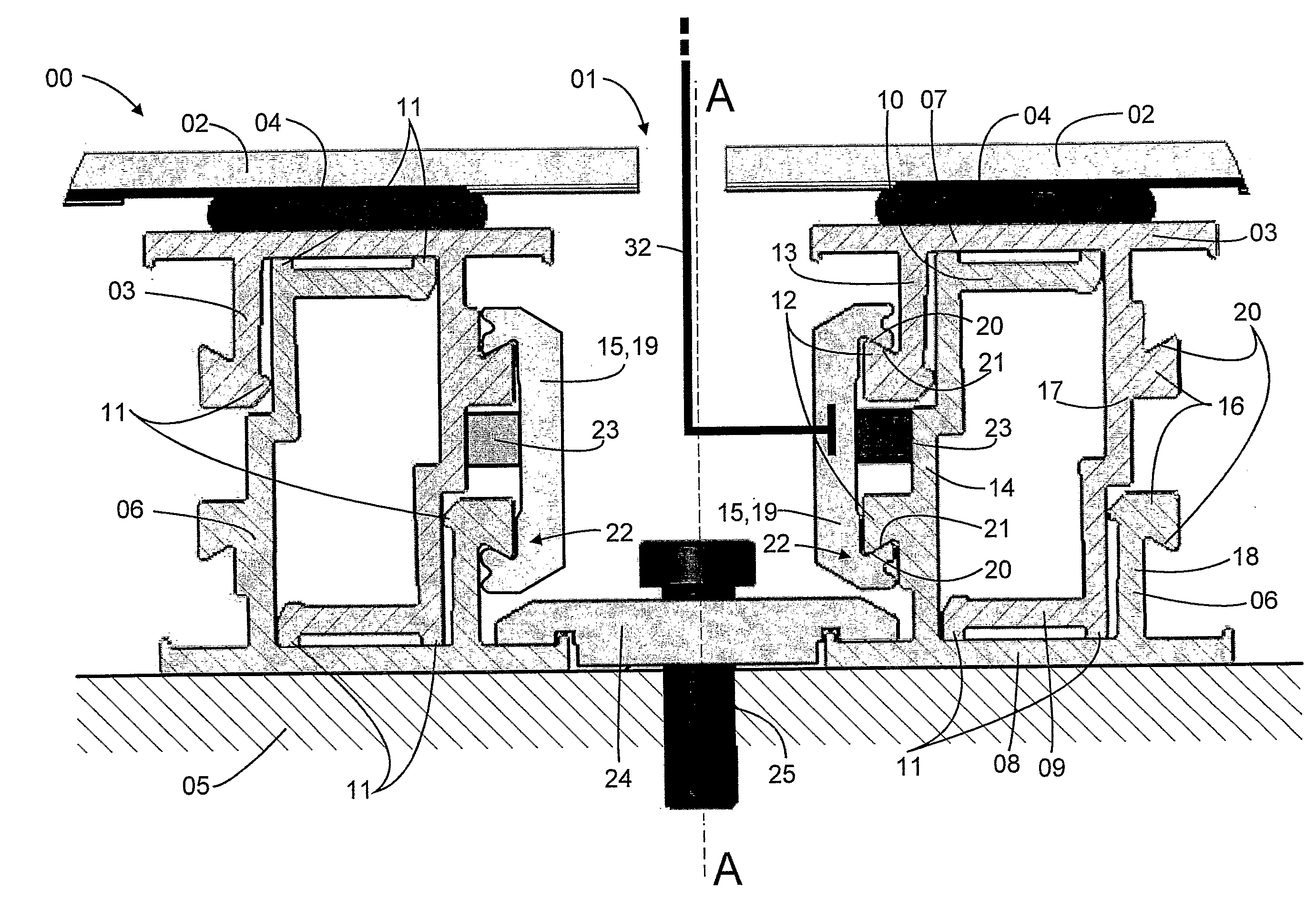
[0015]Embodiments of the photovoltaic unit according to the invention with a connecting element, which protects against lifting off, between module and substrate rails are explained in more detail in the following on the basis of the schematic figures for further understanding of the invention. In the figures:

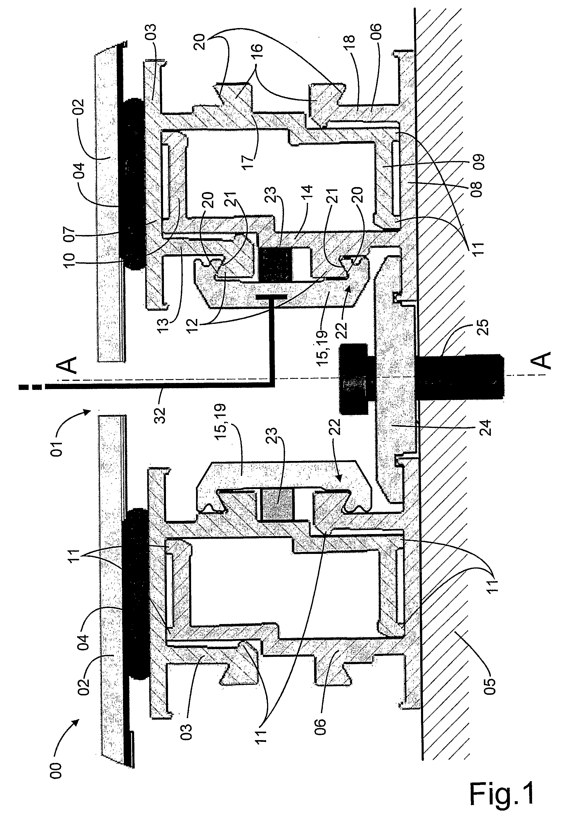
[0016]FIG. 1 shows the cross section of the photovoltaic unit according to the invention in the region of the spacer gap between two solar modules;

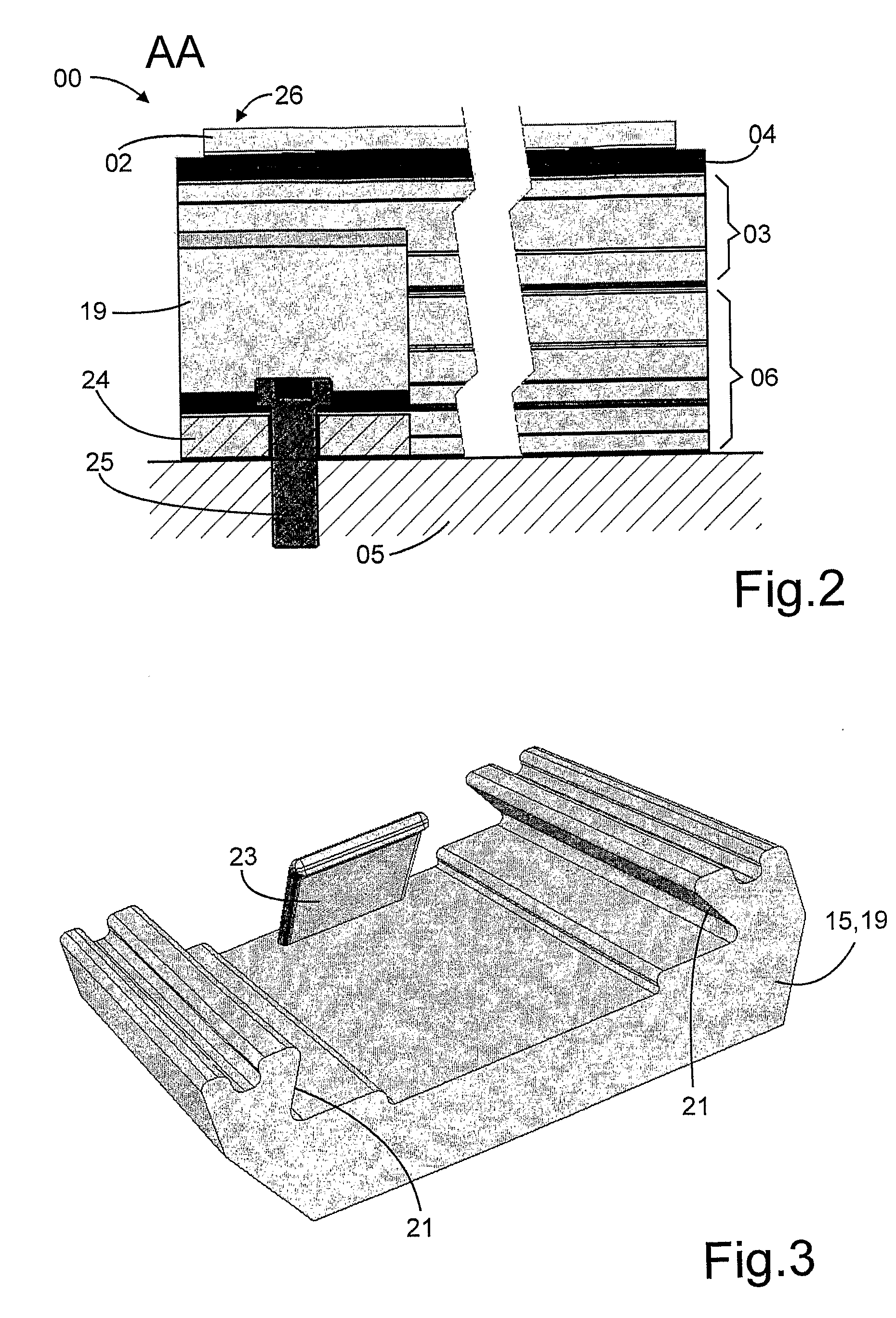
[0017]FIG. 2 shows a sectional representation onto a solar module in the region of the spacer gap;

[0018]FIG. 3 shows a slider in detail; and

[0019]FIG. 4 shows two alternative constructions of sliders.

[0020]FIG. 1 shows a detail from a photovoltaic unit 00 according to the invention in cross section in the region of a spacer gap 01 between two frameless rectangular solar modules 02 (shown cut away from the side), which are arranged in a regular matrix, so that a harmonic undisturbed appearance of the photovoltaic unit results. A modul...


PUM


Abstract

A photovoltaic unit includes a matrix having a plurality of frameless rectangular solar modules, and at least one module rail disposed on an underside of each solar module. Each of the at least one module rail is coupled to a substrate rail, which is releasably connected to a substrate. Each of the at least one module rail and the at least one substrate rail has a guide rail running parallel to an edge of the respective solar module on at least a longitudinal side of the respective rail facing towards an edge region of the solar module. The guide rails on the module and substrate rails are releasably connected to each other by at least one connecting element. A spacer gap of sufficient width for operating the connecting element is provided between adjacent solar modules of the plurality of frameless rectangular solar modules.

Description

[0001]The invention relates to a photovoltaic unit with a matrix made up of frameless rectangular solar modules which have at least two opposite module rails in the edge region on their underside, by means of which they are releasably connected to a substrate.[0002]Among renewable energy sources, photovoltaics offers the widest range of possible applications on account of the modular construction of photovoltaic units from individual solar modules. The main application today is found in the area of consumer use, that is to say, photovoltaic units are used for converting solar energy into electrical energy. To this end, the photovoltaic units must be installed on substrates which have access to sunlight. Here, what is meant is generally open spaces or roofs or facades of buildings. In particular, attention must be paid during installation to securing the solar modules against lifting off due to wind forces. Frameless solar modules show a particularly elegant uniform appearance and ar...

Claims


Application Information

Patent Timeline
Patent Type & Authority Applications(United States)
IPC IPC(8): H01L31/042
CPCF24J2/5205F24J2/5211F24J2/5243F24J2/526H02S20/23Y02B10/12Y02E10/47Y02E10/50H02S20/00F24J2002/4676F24S25/20F24S25/33F24S25/60F24S25/65F24S2025/601H02S20/22H02S20/24Y02B10/10
Inventor SCHWARZE, SASCHA OLIVERSCHAEFER, MAIK
Owner SOLON SE
Why Eureka
Try Eureka