
Polarized eyewear

a polarized eyewear and polarization technology, applied in the field of polarized sunglasses, can solve the problems of inability to maintain the best polarization axis for viewing through polarized eyewear, difficult to compensate, and inevitable amount of viewer head movement, so as to reduce back reflection

Active Publication Date: 2010-11-11
SOL GRID
View PDF4 Cites 68 Cited by
  • Summary
  • Abstract
  • Description
  • Claims
  • Application Information

AI Technical Summary

Benefits of technology

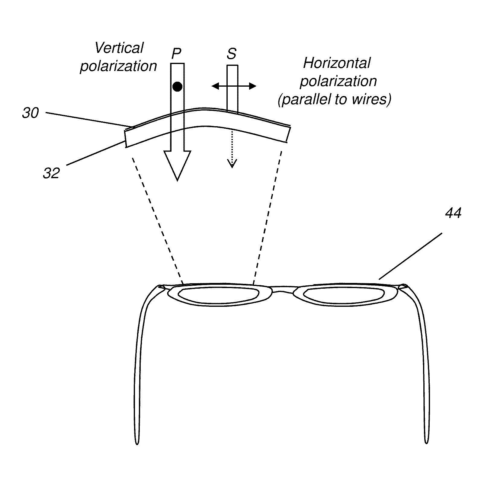
[0017]It is an advantage of the present invention that it provides polarized eyewear that allows adaptation to highly curved lens designs and is generally more flexible and adaptable than the conventional stretched-substrate polarizer solutions. It is a further advantage of the present invention that it provides polarized eyewear with reduced back reflection due to light from behind the lenses.
[0018]A further advantage of the present invention relates to the capability to change the relative opacity of an eyeglass lens or related eyewear to accommodate incident light conditions or viewer preference.

Problems solved by technology

However, in practice, maintaining the best polarization axis for viewing through polarized eyewear can be difficult.
Certainly, some amount of viewer head movement is inevitable and can be difficult to compensate while maintaining desired polarization.
But a more significant problem for maintaining the preferred polarization axis relates to lens shape and sunglass design.
Conventional polarizers do not easily adapt to “wraparound” lens shapes or to more highly curved spherical and “sun-lens” designs.
Designs that require more than minimal bending and curving of the polarized plastic and designs with curvature about more than one axis tend to cause inconsistent and non-uniform stretching of the polarizer material and can easily warp and degrade the performance of the polarizer film.
A stretched pattern of molecules can be warped out of their intended alignment by any type of shaping operation, making the corresponding polarizer less effective, compromising the extinction ratio in an irregular fashion over the lens surface, leading to an inconsistent polarization pattern across the field of view, and even introducing image aberrations and artifacts into the lens.
In extreme cases, this effect can be distracting, can lead to image distortion, and might even be hazardous for the viewer.
Yet another problem with conventional polarizer fabrication relates to waste.
Because of the nature of handling thin plastic substrates, stretching of the polarizer film itself is a relatively imprecise process that is difficult to control, and the end-product is often subject to non-uniformity.
It has proven to be difficult to provide the uniform stress pattern needed for maintaining a polarization axis and relative success or failure may not be known until after fabrication has been completed.
This, in turn, leads to reduced yields.
Because of these problems, polarized lens material, available only for designs with limited curvatures, more uniform cylindrical curvatures, and simpler shapes, is often difficult to adapt to eyewear design and consumer tastes.
Difficulties in controlling the polarization axis for any particular lens shape constrain the ability of lens designers to take advantages of inherent strengths and benefits of polarizers for the eyeglass wearer.
One drawback relates to relatively slow response times, making photochromic behavior less desirable where brightness transitions are sudden and extreme, or where light is intense over only a small portion of the field.
Another problem relates to poor spectral response of many photochromic materials for light outside the UV range.
Because of these and related problems, there is limited applicability of photochromic benefits to industrial, transportation, or defense safety using conventional design approaches.

Method used


Image

  • Polarized eyewear
  • Polarized eyewear
  • Polarized eyewear

Examples


Embodiment Construction

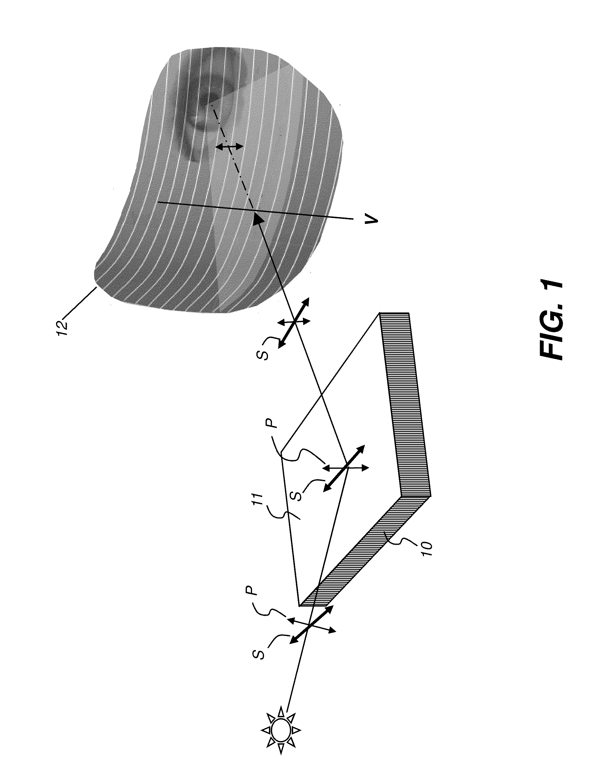
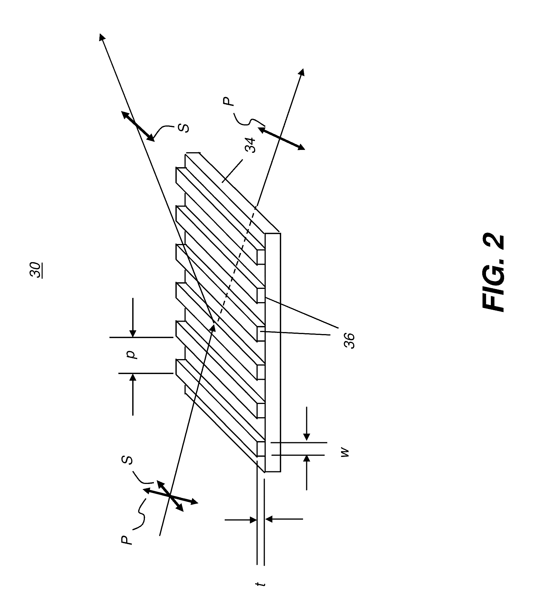
[0051]Elements not specifically shown or described may take various forms well known to those skilled in the art. Figures shown and described herein are provided in order to illustrate key principles of operation and component relationships along their respective optical paths or fabrication techniques according to the present invention and are not drawn with intent to show actual size or scale. Some exaggeration may be necessary in order to emphasize basic structural relationships or principles of operation.

[0052]In the context of the present disclosure, the term “complex index of refraction” applies where the index of refraction for a material contains both a real component designated commonly as n and a significant imaginary (−i) component, commonly designated as k. Imaginary component k can be considered to be significant where the ratio of k to n satisfies:

kn≥0.2

[0053]For example, metallic aluminum has a complex index of refraction, with its imaginary part k given by k=6.69 and...


PUM


Abstract

An article of polarized eyewear has a lens, with a first substrate lens material transparent to visible light and a pattern of elongated structures formed from at least a second material having a complex index of refraction, wherein the second material is deposited directly onto a curved surface of the first substrate lens material. A pitch between adjacent elongated structures is less than 300 nm and a width of each elongated structure is less than 90% of the pitch. A photochromic material is deposited onto the polarized eyewear.

Description

CROSS REFERENCE TO RELATED APPLICATIONS[0001]The present application is a continuation-in-part of commonly assigned co-pending U.S. patent application Ser. No. 12 / 248,342 filed 9 Oct. 2008 by Matera et al. and entitled POLARIZED EYEWEAR.FIELD OF THE INVENTION[0002]The present invention relates generally to polarizing sunglasses and other types of eyewear and more particularly relates to polarized eyewear embodiments in 3D imaging and in variable opacity eyewear.BACKGROUND OF THE INVENTION[0003]Polarized lenses have been used in sunglasses and other types of eyewear for a number of years and have proved to be of particular value in reducing glare and other potentially irritating effects for the wearer. The conventional fabrication method for polarizer material uses a layering in which a sheet of polarized film material is sandwiched or laminated between outer layers of a glass or plastic. The polarizer material itself is a thin sheet of polymer that has its molecules aligned or orien...

Claims


Application Information

Patent Timeline
IPC IPC(8): G02C7/12G02F1/1335
CPCB29D11/00634G02C7/12G02B5/3058G02B5/23
Inventor MATERA, PASQUALEKESSLER, DAVID
Owner SOL GRID
Learn More