Bidirectional optical link over a single multimode fiber or waveguide

a multimode fiber or waveguide technology, applied in the field of multimode fibers, can solve the problems of reducing the service life of the optical link, and increasing the cost of wavelength separation optics

Active Publication Date: 2010-11-11
ANALOG DEVICES INC
View PDF47 Cites 7 Cited by
  • Summary
  • Abstract
  • Description
  • Claims
  • Application Information

AI Technical Summary

Problems solved by technology

The 6 dB link loss is significant if the light is either traveling long distances or in case of high speed links when there is often insufficient link margin.
Wavelength separation optics generally adds cost.
Even if a clever transceiver design overcomes the various hurdles mentioned above, one still has a logistical challenge.
This is a real market challenge.
This is a not a very robust solution since lasers are high gain devices and it is hard to maintain precise attenuation while maintaining adequate link margin.
This means that it is difficult to imagine links constructed with multimode fibers and customer made patch cords in the field.

Method used


Image

  • Bidirectional optical link over a single multimode fiber or waveguide
  • Bidirectional optical link over a single multimode fiber or waveguide
  • Bidirectional optical link over a single multimode fiber or waveguide

Examples


Embodiment Construction

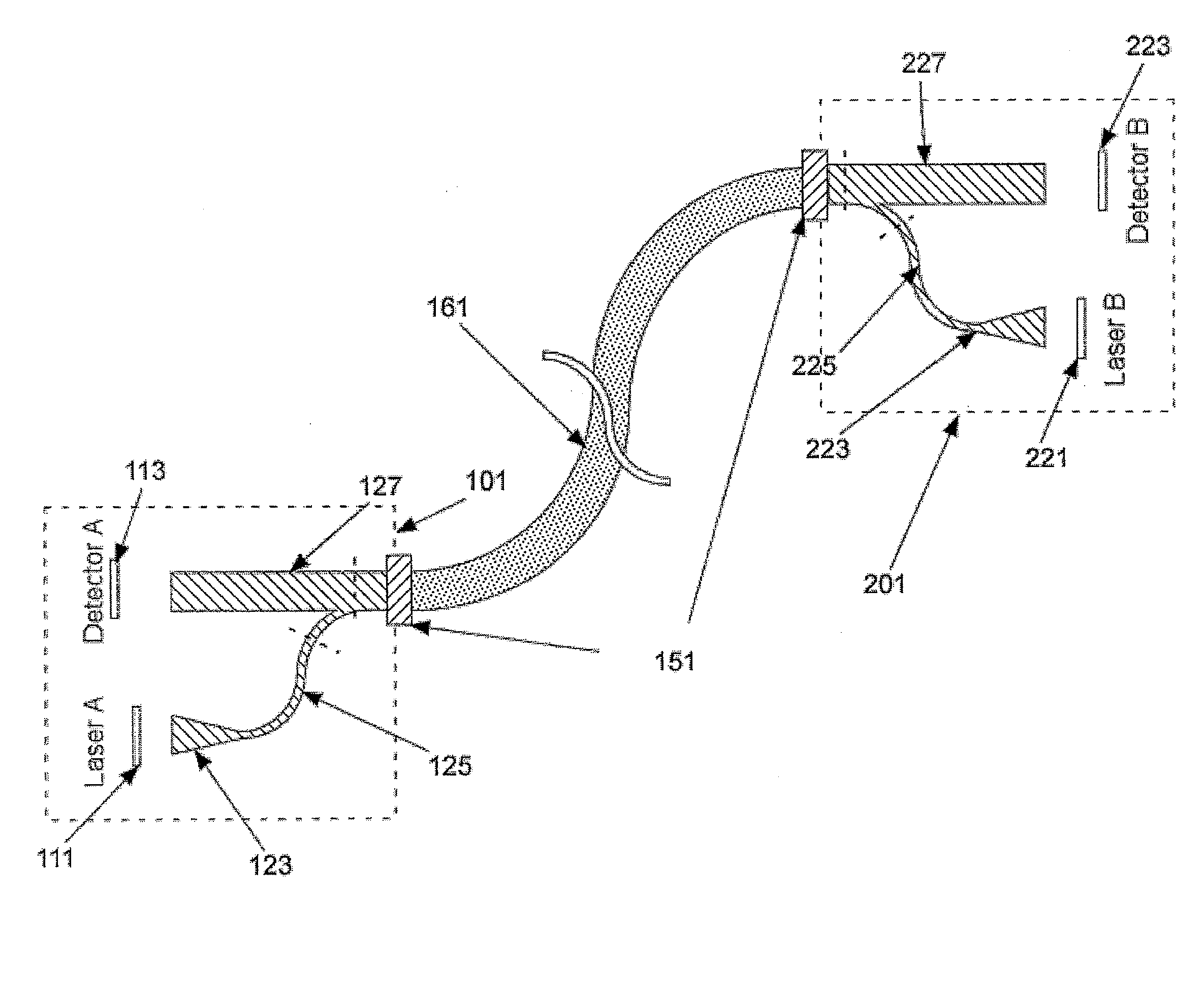
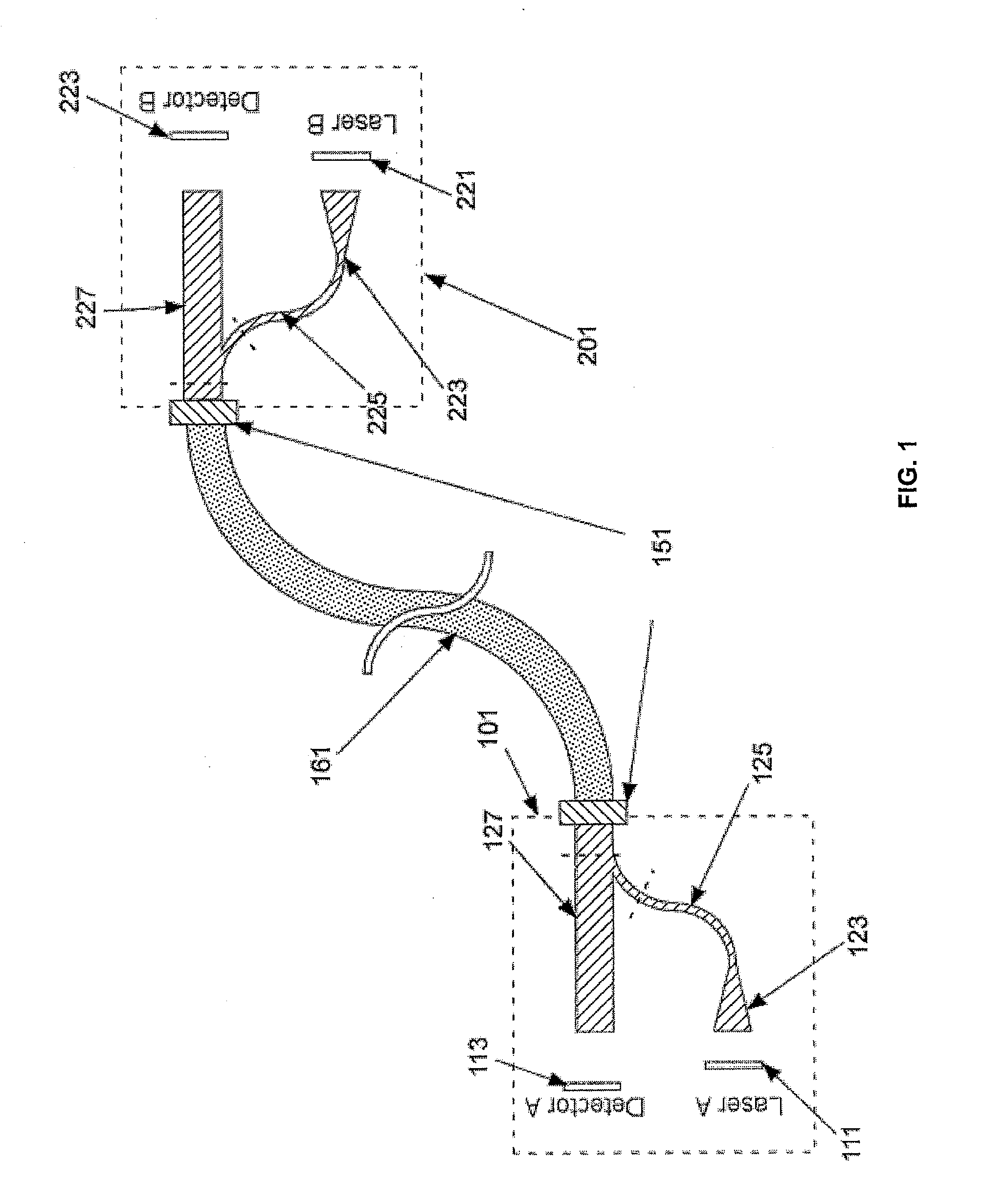
[0018]The present invention provides the capacity for coupling a laser from transmitter A to Receiver B on the other side with very low loss while simultaneously providing very high loss to the Transmitter B (>40 dB) to unconditionally maintain stability of both the lasers. This is achieved either inside or near each of the transceivers. For the end user, a standard single optical connector is presented. All transmitters and receivers are identical. There is no stringent requirement on the optical fiber inserted between the transceiver by the user. The same fiber used today with connectors will work with the invention.

[0019]The object and advantages mentioned above in the present invention are achieved by using asymmetric mode-coupling in multimode fibers. In short, a single transverse mode laser (edge emitter or a single mode VCSEL) is coupled to a multimode fiber. This multimoded section is tapered so as to allow a single mode transmission. This single mode is coupled to a multimo...


PUM


Abstract

A transceiver for use in a bidirectional optical communication link over a multimode channel is provided. The transceiver includes a single transverse mode light source in a transmitter. A waveguide or fiber based bidirectional coupler projects the transmitter mode to the high modes of the multimode channel. A detector coupled to predominantly all the modes of the channel via the waveguide or fiber based bidirectional coupler.

Description

BACKGROUND OF THE INVENTION[0001]The invention relates to the field of multimode fibers, and in particular to bidirectional optical link over a single multimode fiber or waveguide.[0002]Most optical links are point-to-point links. The present practice is to have two fibers—one for transmission and the other for reception of light. Two fibers are used to primarily avoid any coupling of two lasers on the two sides of the link. It is possible to construct a bidirectional link over the same fiber without making lasers unstable if “uplink” used a different wavelength then “downlink”. Now it is possible to use a simple 3 dB beam splitter at each end. Because the wavelengths are different, the lasers do not couple and hence the link is made. In this case, there will be 6 db (3 dB each end) insertion loss from the beam splitters. This may not be a problem if there is sufficient transmit laser power and receiver sensitivity.[0003]The 6 dB link loss is significant if the light is either trave...

Claims


Application Information

Patent Timeline
Patent Type & Authority Applications(United States)
IPC IPC(8): H04B10/00
CPCG02B6/4246H04B10/40H01L31/12
Inventor DELIWALA, SHRENIK
Owner ANALOG DEVICES INC
Why Eureka
Try Eureka