Cooling an Electrically Controlled Turbocharger

an electrically controlled, turbocharger technology, applied in the direction of liquid fuel engines, positive displacement liquid engines, piston pumps, etc., can solve the problems of affecting the entire structure, few diesel engines in new vehicles today operate without turbochargers, and exhaust flow may not drive the turbocharger sufficiently

Active Publication Date: 2010-11-11
ECOMOTORS INT
View PDF29 Cites 110 Cited by
  • Summary
  • Abstract
  • Description
  • Claims
  • Application Information

AI Technical Summary

Problems solved by technology

Few diesel engines in new vehicles today operate without a turbocharger.
At low engine revolutions, the exhaust flow may not drive the turbocharger sufficiently to obtain sufficient compressor rotation to force enough air from the compressor to the engine's intake manifold.
Significant challenges still exist so that the motor continues to function in the harsh, high temperature, high speed environment of a turbocharger.
The high gas temperatures on the turbine side of a turbocharger (≈1050° C. in gasoline engines; lower in diesel engines), adversely affects the entire structure.
In addition, the compressor side of the turbocharger causes significant temperature increases because the increase in air pressure raises the air temperature, up to an increase of about 180° C. Moreover, resistance heating in the motor's stator adds to the turbocharge

Method used


Image

  • Cooling an Electrically Controlled Turbocharger
  • Cooling an Electrically Controlled Turbocharger
  • Cooling an Electrically Controlled Turbocharger

Examples


Embodiment Construction

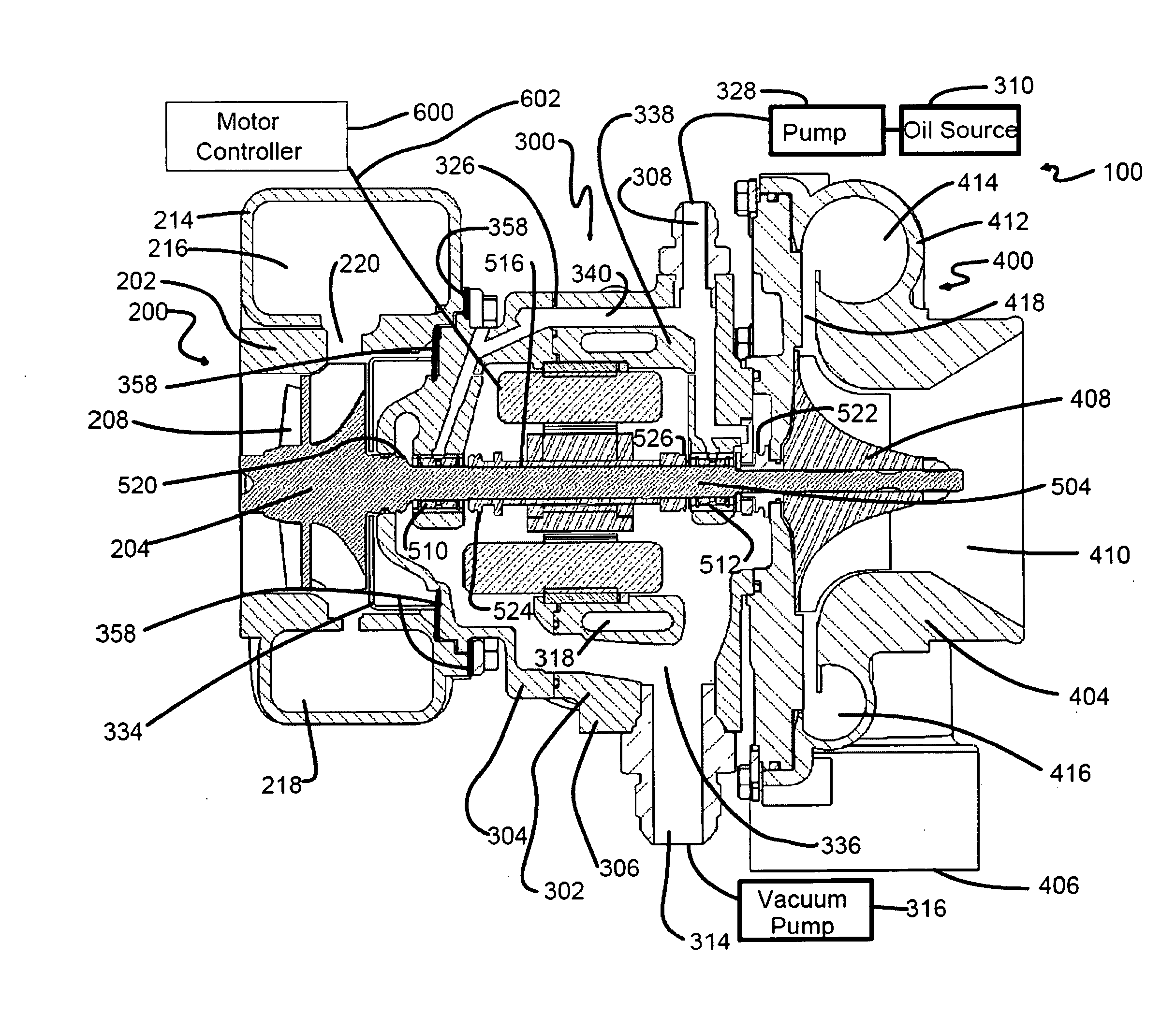
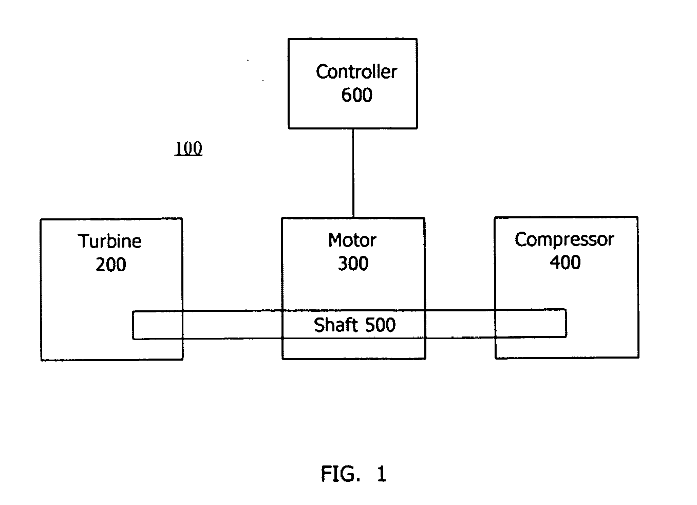
[0034]In the FIG. 1 block diagram, electrically controlled turbocharger 100 comprises a turbine 200, a compressor 400, a motor 300, a shaft assembly 500 and a controller 600. Motor 300 may be disposed between the turbine 200 and compressor 400, and shaft assembly 500 interconnects turbine 200, compressor 400 and motor 300. The turbine and compressor may be respectively secured to the motor to form a single unit. The turbine, compressor, motor and shaft assembly may have other relative physical arrangements. The controller 600 controls operation of the motor 300 through connection 602 (FIG. 5).

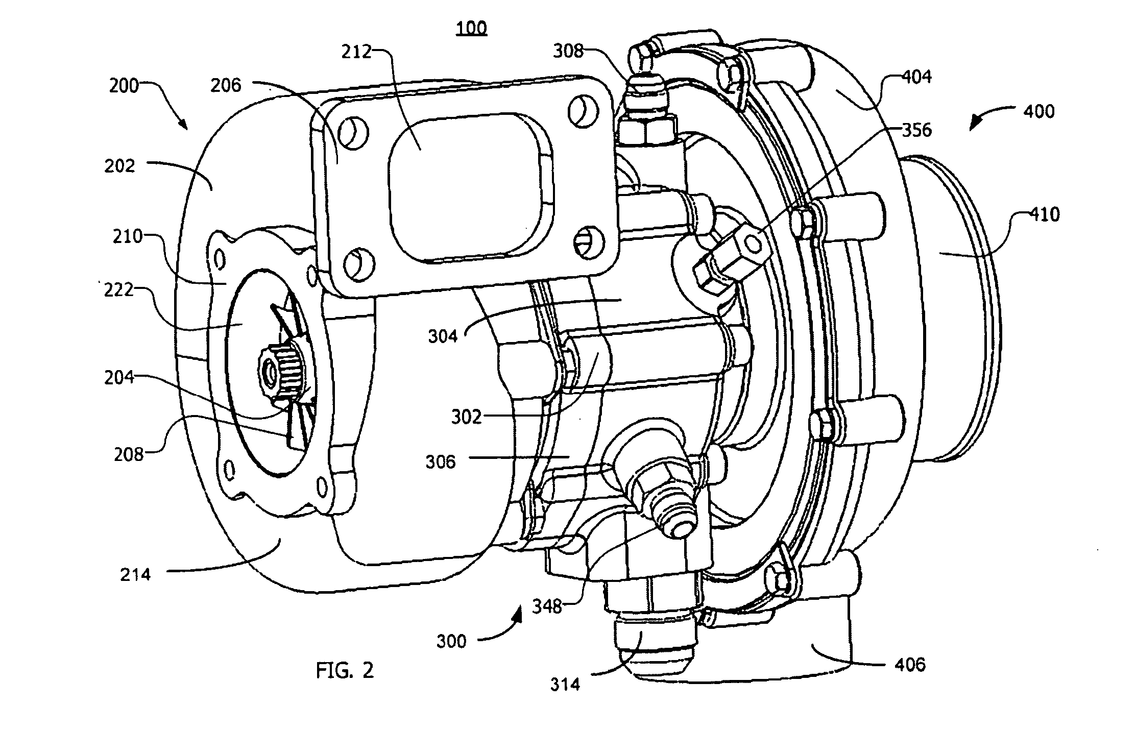
[0035]In the FIGS. 2 and 3 external perspective views of the electrically controlled turbocharger 100, housing 202 of turbine 200 includes inlet flange 206 at inlet 212. Exhaust gases from an engine (not shown) enter the inlet and flow through volute 214 (see also FIGS. 4 and 5). The volute may provide a spiral path for the incoming exhaust gases and, therefore, may have a decreasing dimension ...


PUM


Abstract

An electrically controlled turbocharger has a motor mounted on a shaft in a motor housing between a turbine and compressor. Oil is sprayed onto the motor stator to cool the stator. An oil gallery is disposed above the stator to receive lubricating oil and contains apertures that perform as jets to allow oil to be sprayed directly on the motor stator. A coolant jacket is formed in the turbocharger housing between the turbine and the motor to allow liquid coolant to circulate therein and dissipate heat from the turbine end prior to reaching the motor components. Other embodiments provide for a stator component to be submerged in flowing cooling oil.

Description

RELATED APPLICATIONS[0001]This application is a continuation in part of U.S. Ser. No. 12 / 417,568 filed Apr. 2, 2009 and is related to PTC application PCT / US2010 / 020707 filed Jan. 12, 2010, each of which are incorporated herein by reference.BACKGROUND[0002]1. Field[0003]Electrically controlled, engine exhaust gas turbochargers.[0004]2. Description of the Related Art[0005]Turbochargers use an engine's own exhaust gases to compress and, thus, increase the volume of air entering the engine to increase engine efficiency.[0006]Engine exhaust gases from the exhaust manifold drive a turbine at high speed. Turbine rotation rotates a shaft, which is shared with a compressor. The compressor compresses outside air and delivers it to the engine's intake manifold. Compression causes more air and thus more oxygen to enter each combustion cylinder. Consequently, the engine operates more efficiently, at higher horsepower and torque and with lower cylinder displacement than conventionally aspirated e...

Claims


Application Information

Patent Timeline
IPC IPC(8): F04B49/06F03B11/00F04D29/58
CPCF01M11/02F01M2011/021F01P2060/12F02B29/0412F02B29/0475F02B37/10F02B39/10F02B39/14F02C6/12F05D2220/40F05D2220/76Y02T10/12
Inventor HIPPEN, WILLLAIMBOECK, FRANZGARRARD, TYLER
Owner ECOMOTORS INT
Why Eureka
Try Eureka