Patient specific alignment guide for a proximal femur

Active Publication Date: 2010-11-11
SMITH & NEPHEW INC
View PDF30 Cites 243 Cited by
  • Summary
  • Abstract
  • Description
  • Claims
  • Application Information

AI Technical Summary

Benefits of technology

[0008]Certain embodiments of the invention constitute alignment guides for aligning instrumentation on a proximal femur. Such guides can include a neck portion configured to wrap around a portion of the neck of the femur, a head underside portion configured to abut a disto-lateral portion of the femoral head and a medial head portion with arms that are configured to overlie a medial and superior portion of the head. Portions of the guide can have an inner surface that is generally a negative of the femoral bone and/or cartilage of a specific patient that the guide overlies; such surfaces can be formed using data obtained from the specific patient by conventional imaging devices, and using computer aided design and manufacturing techniques. The neck portion can be configured to stabilize the guide rotationally

Problems solved by technology

Current instrumentation is generally hard to learn, difficult to use, and time consuming.
However, the art generally does not specifically focus on the important

Method used


Image

  • Patient specific alignment guide for a proximal femur
  • Patient specific alignment guide for a proximal femur
  • Patient specific alignment guide for a proximal femur

Examples


Embodiment Construction

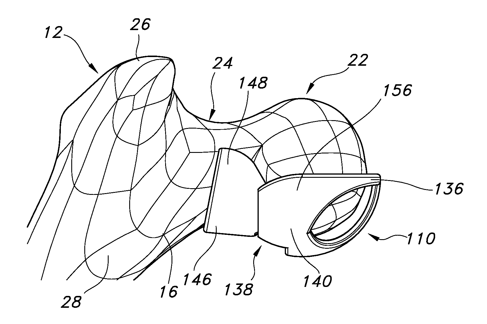
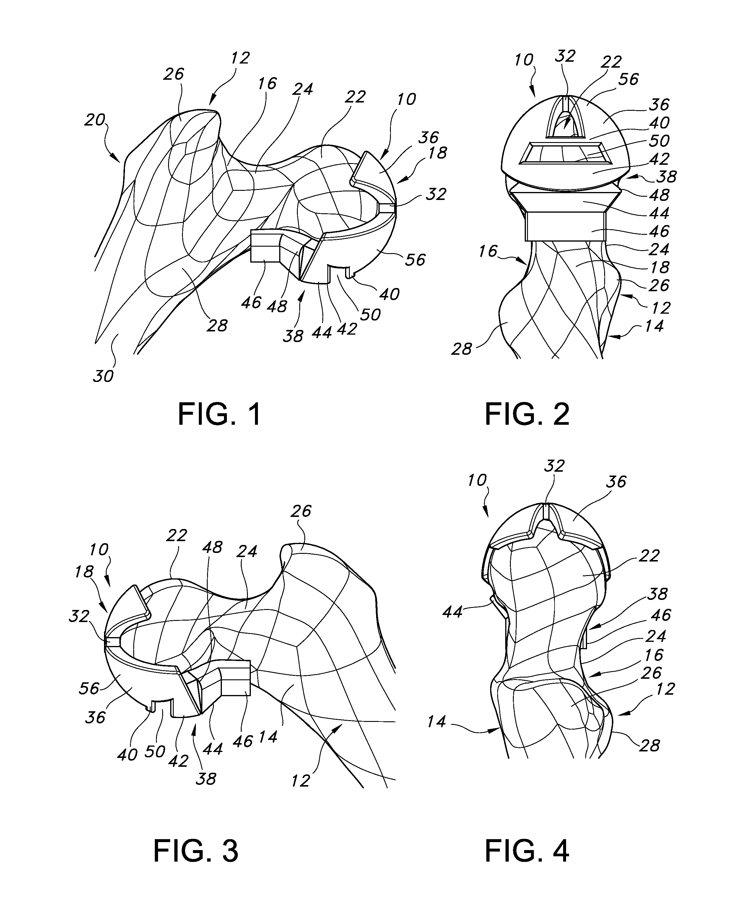
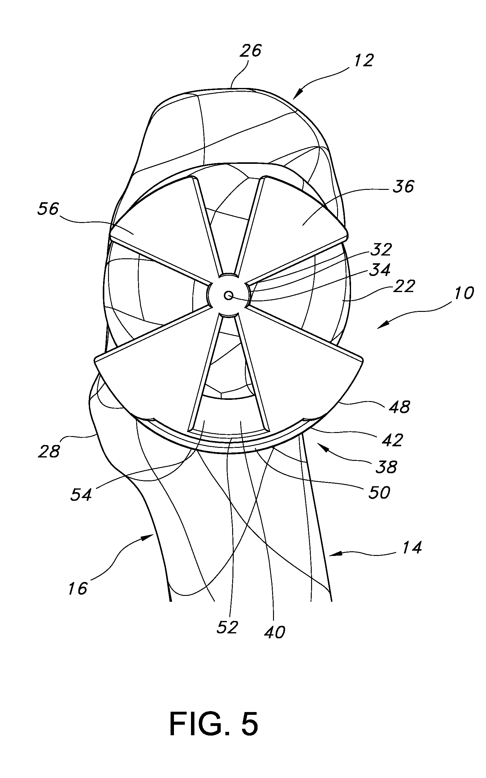
[0046]FIGS. 1-5 illustrate views of a patient specific alignment guide 10 attached to a femur 12 (in this case a left femur) according to an embodiment of the invention. FIG. 1 is a posterior view of the guide and the femur. FIGS. 2-5 are a distal view, anterior view, proximal view and medial view, respectively, of the guide 10 and femur 12.

[0047]The alignment guides of all the embodiments are generally meant to locate an axis into the head and neck of the femur 12 in order to position the axis and form a bore that can be used with subsequent instrumentation for a hip surgery, for example a hip resurfacing surgery such as the procedure for preparing anatomy for acceptance of a Birmingham Hip Resurfacing® (BHR) implant by Smith & Nephew, Inc. This axis, because the neck tapers down, must be accurately located in order to align the implant properly. Moreover, proper placement on the head of the femur must be found in order to avoid notching portions of the femoral neck during the resu...


PUM

PropertyMeasurementUnit
Sizeaaaaaaaaaa
Shapeaaaaaaaaaa

Abstract

An alignment guide for aligning instrumentation along a proximal femur includes a neck portion configured to wrap around a portion of the neck of the femur, a head underside portion configured to abut a disto-lateral portion of the femoral head and a medial head portion configured to overlie a medial portion of the head. Portions of the guide can have an inner surface generally a negative of the femoral bone of a specific patient that the guide overlies; such surfaces can be formed using data obtained from the specific patient. The neck portion can be configured to rotationally stabilize the guide by abutting and generating a first gripping force on the neck. The femoral head portions can be configured to grip the head portion of the femur and can support a bore guide that is configured to guide an instrument to the femur in a specified location and along a given axis.

Description

CROSS REFERENCE TO RELATED APPLICATIONS[0001]This application claims the benefit of U.S. Provisional Application No. 61 / 176,455, filed May 7, 2009, titled “Patient Specific Alignment Guide for a Proximal Femur” and U.S. Provisional Application No. 61 / 230,064, filed Jul. 30, 2009, titled “Patient Specific Alignment Guide.” Both of these Provisional Applications are expressly incorporated herein by this reference.BACKGROUND OF THE INVENTION[0002]1. Field of the Invention[0003]This invention relates generally to instruments for bone modifications at a hip joint and, more particularly, for instruments designed for a patient's specific bone and cartilage.[0004]2. Related Art[0005]Current instrumentation is generally hard to learn, difficult to use, and time consuming. Costs may be reduced by reducing the time required to perform the surgery, as well as requiring fewer instruments. Additionally, patient specific instrumentation may also limit the invasiveness of instruments, may provide f...

Claims


Application Information

Patent Timeline
IPC IPC(8): A61B17/56B23P17/04
CPCA61B17/175Y10T29/49A61B2019/508A61B2019/505A61B2034/105A61B2034/108
Inventor SNIDER, ASHLEY M.NISHIMOTO, BRYAN I.DEMMER, MATTHEW J.MEHL, DAVIDBOURNE, TIMOTHY J.GATEWOOD, JAMESFREDERICK, PHILLIPSALEHI, ABRAHAM B.
Owner SMITH & NEPHEW INC
Why Eureka
Try Eureka