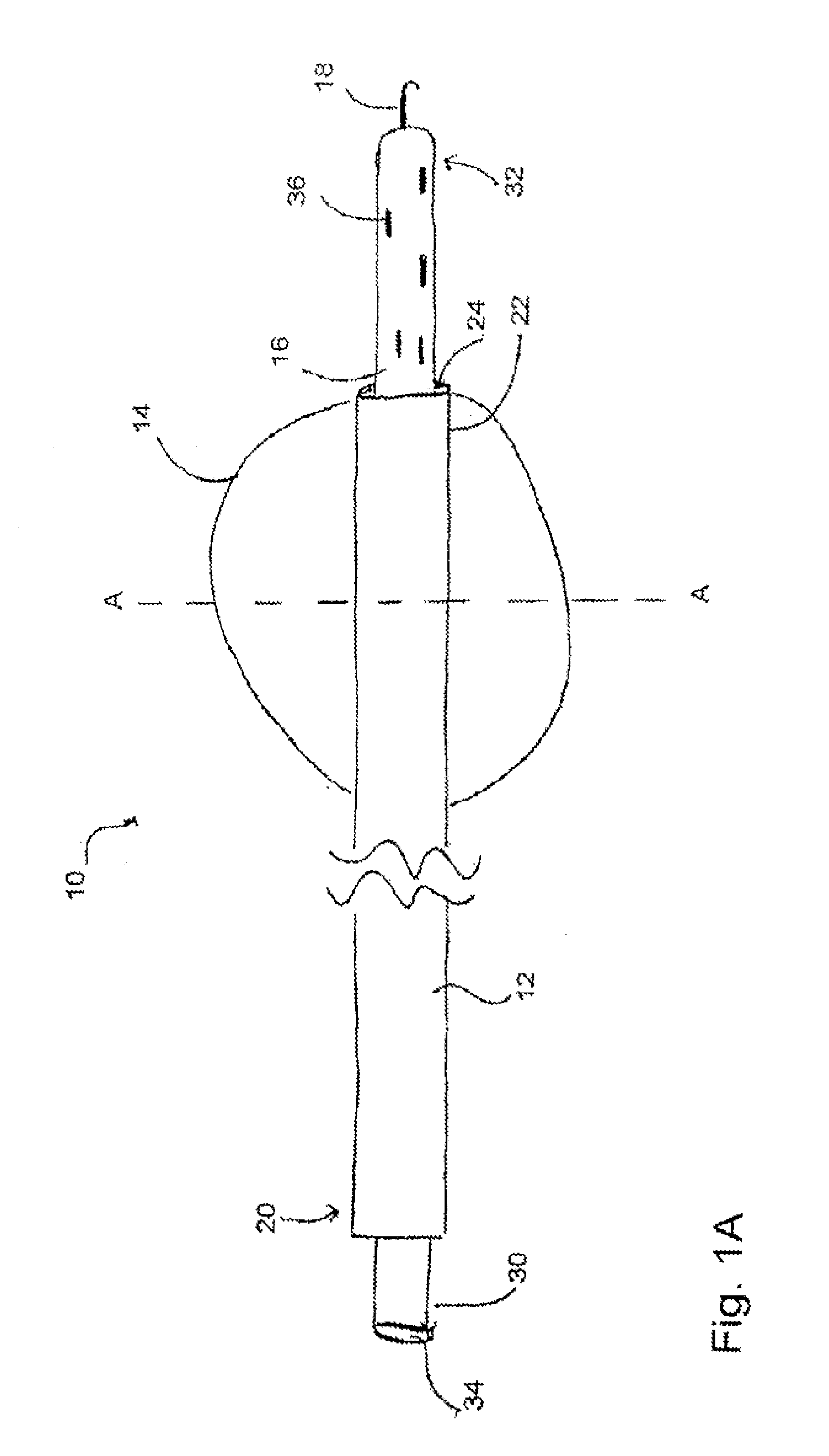
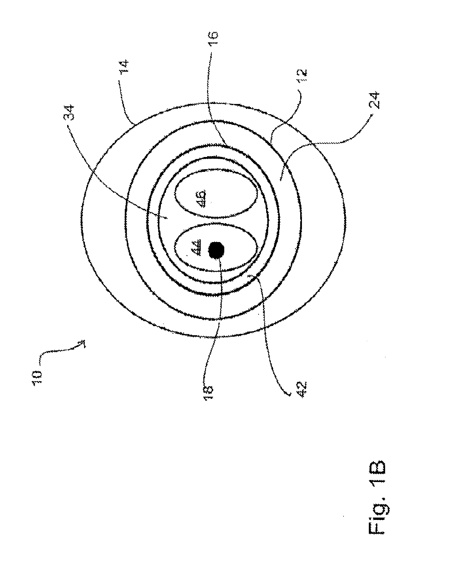
[0009]In another embodiment, the second device further comprises a shaft having a distal end, wherein the loop is coupled to the shaft at or near the distal end of the shaft. In yet another embodiment, at least one aperture is defined within the first tube at or near the balloon, the at least one aperture sized and shaped to allow a gas and / or a liquid to be introduced and / or removed from the balloon. In an additional embodiment, the balloon of the first device, when inserted into an atrial appendage cavity, is capable of inflation to displace blood present within the atrial appendage cavity. In yet an additional embodiment, the balloon of the first device, when positioned at an entrance of an atrial appendage cavity, is capable of inflation to occlude the entrance of the atrial appendage cavity, and wherein suction from a suction source operably coupled to the first tube facilitates the removal of blood present within the atrial appendage cavity.
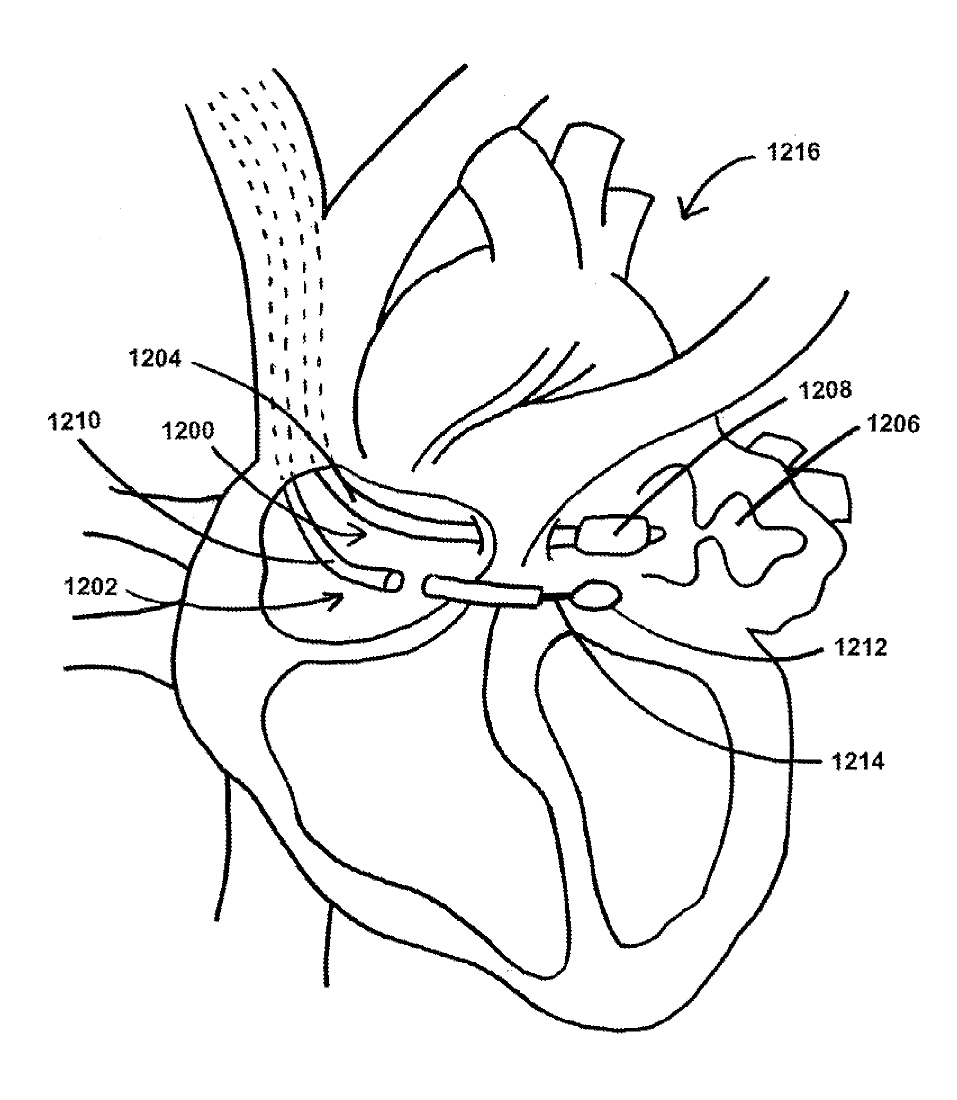
[0014]In at least one method for occluding an atrial appendage of a heart of a patient, the method comprises the steps of introducing at least a portion of a first device into an entrance of an atrial appendage cavity, the first device comprising a first tube having a proximal end and a distal end and a balloon capable of inflation and deflation, the balloon coupled to the first tube at or near the distal end of the first tube, introducing at least a portion of a second device into a
pericardial space surrounding the heart, the second device comprising a second tube sized and shaped for
insertion into the
pericardial space surrounding the heart, the second tube comprising a lumen extending at least partially from a second tube distal end to a second tube proximal end and a loop sized and shaped to fit at least partially within the lumen of the second tube, wherein the loop is capable of protraction from the second tube distal end, positioning the balloon of the first device at least partially within the entrance of the atrial appendage cavity, inflating the balloon to substantially prevent blood from flowing in or out of the atrial appendage cavity, applying suction from the proximal end of the first tube to displace blood residing within the atrial appendage cavity, positioning the loop of the second device around the
left atrial appendage, tightening the loop around the
left atrial appendage, deflating the balloon to allow for ultimate removal of the first device from the entrance of the atrial appendage cavity, and separating the loop from the shaft so that the loop remains positioned and tightened around the
left atrial appendage.
[0015]In another method for occluding an atrial appendage of a heart of a patient, the method comprises the steps of providing a first device, the first device comprising a first tube having a distal end and a balloon capable of inflation and deflation, the balloon coupled to the first tube at or near the distal end of the first tube, the balloon sized and shaped for
insertion into an entrance of a left atrial appendage cavity, providing a second device, the second device comprising a second tube sized and shaped for
insertion into a pericardial space surrounding the heart, the second tube comprising a lumen extending at least partially from a second tube distal end to a second tube proximal end, a loop sized and shaped to fit at least partially within the lumen of the second tube, wherein the loop is capable of protraction from the second tube distal end, and a shaft having a distal end, wherein the loop is coupled to the shaft at or near the distal end of the shaft, introducing the first device into the patient using femoral or jugular
venous puncture, advancing the first device within the patient from
a site of femoral or jugular
venous puncture so that the distal end of the first tube of the first device is positioned within a
right atrium of the heart,
puncturing a septum between the
right atrium and a
left atrium of the heart using the first device, advancing the distal end of the first tube of the first device through the punctured septum, positioning the distal end of the first tube at the entrance of the left atrial appendage cavity so that the balloon is at least partially positioned within the entrance of the left atrial appendage cavity, introducing the second device into the patient, advancing the second device within the patient to a location at or near a targeted tissue on an interior wall of the heart,
puncturing the targeted tissue using the second device, advancing the distal end of the second tube of the second device through the punctured targeted tissue into a pericardial space to a location at or near the left atrial appendage, inflating the balloon to substantially prevent blood from flowing in or out of the left atrial appendage cavity, applying suction from the proximal end of the first tube to displace blood residing within the left atrial appendage cavity, positioning the loop of the second device around the left atrial appendage, tightening the loop around the left atrial appendage, deflating the balloon to allow for ultimate removal of the first device from the entrance of the atrial appendage cavity, and separating the loop from the shaft so that the loop remains positioned and tightened around the atrial appendage.
[0016]In another embodiment, the method further comprises the step of removing the first device from the heart. In yet another embodiment, the method further comprises the step of removing the second tube from the pericardial space surrounding the heart. In an additional embodiment, the step of introducing at least a portion of a first device into an atrial appendage cavity is performed after the patient has been administered
local anesthesia. In yet an additional embodiment, the step of introducing at least a portion of a first device into an atrial appendage cavity is performed after the patient has been administered a
sedative allowing the patient to remain conscious as the method for occluding the atrial appendage is performed.

