Fluid distribution element for a fluid-conducting device, in particular for multichannel-like fluid-conducting appliances which are nested in each other

a technology of fluid-conducting appliances and fluid-conducting devices, which is applied in the direction of laminated elements, fixture plate conduit assemblies, lighting and heating apparatus, etc., can solve the problems of time-consuming and labor-intensive, multi-stage methods, and formation of cracks,

Inactive Publication Date: 2010-11-18
FRAUNHOFER GESELLSCHAFT ZUR FOERDERUNG DER ANGEWANDTEN FORSCHUNG EV
View PDF10 Cites 9 Cited by
  • Summary
  • Abstract
  • Description
  • Claims
  • Application Information

AI Technical Summary

Benefits of technology

[0013]The fluid distribution element according to the invention has a very low spatial requirement and simplifies the interlinked connection of multichannel pipes for the purpose of construction of a compact assembly for heat exchange. In particular the fluid distribution element according to the invention can be produced in a constructionally simple manner thus without, as in the state of the art, an increased risk of leakage arising at the interpenetration points. In order to prevent in addition possible pressure losses, the construction of the fluid-conducting device can be effected advantageously by means of the fluid distribution elements such that bionic attachments are followed in the line of the channel.
[0016]In addition to the economical production with the help of the described roll-bonding method with metal sheets, such a fluid-distribution element according to the invention can be produced economically and in a fully automated manner even by means of glueing of prefabricated plastic material or metal parts in which half-channels are already prefabricated.
[0019]The previously described mode of production for the individual fluid distribution elements or the entire fluid-conducting assembly which has the arrangement of fluid distribution elements offers, in addition to the advantage that no soldering or welding operations are necessary, also the advantage that they or it can be produced with the same conventional economical metals or plastic materials as the multichannel pipes themselves which are to be connected. The connections on the end-side of the individual pipe supply lines are advantageously shaped with a circular cross-section and chosen with a standard inner width so that a connection to conventional lines and male fittings can be effected without difficulty. The cross-section of the channels can remain constant along the stretch so that pressure or throughflow remain constant or are varied so that physical phenomena, such as e.g. evaporation or condensation, can be assisted specifically. The distributor coupling or fluid distribution element according to the invention is hence characterised by a simple construction and simple production and also by low material costs. The shape of the plates can be arbitrary (viewed in the layer plane), for example in a rectangular shape or even in a polygonal shape.

Problems solved by technology

Such a production method is however multistage and not completely automatable: it requires inter alia sealing of the penetrated channel, generally by a solder, the thermal expansion behaviour of which is different from that of the channel material.
With high thermal stressing, this can lead to the formation of cracks.
As a result, the requirement arises for a more comprehensive leakage test which is time-consuming and labour-intensive.
In the field of heat pumps, it applies that, in addition to the costs for the plant itself, increased production costs arise due to the necessary acquisition of a heat source.
However, the efficiency of such a heat pump is reduced because the heat source is subject to much stronger seasonally conditioned temperature variations.
This method is technically very complex and not completely automatable.2. The outer pipe is already preformed with respect to lamellae.
As a result, problems result in particular in automated manufacture because of the complex geometry of the interpenetrating regions of the pipe wall in the pipe bends.

Method used


Image

  • Fluid distribution element for a fluid-conducting device, in particular for multichannel-like fluid-conducting appliances which are nested in each other
  • Fluid distribution element for a fluid-conducting device, in particular for multichannel-like fluid-conducting appliances which are nested in each other
  • Fluid distribution element for a fluid-conducting device, in particular for multichannel-like fluid-conducting appliances which are nested in each other

Examples


Embodiment Construction

[0025]There are shown:

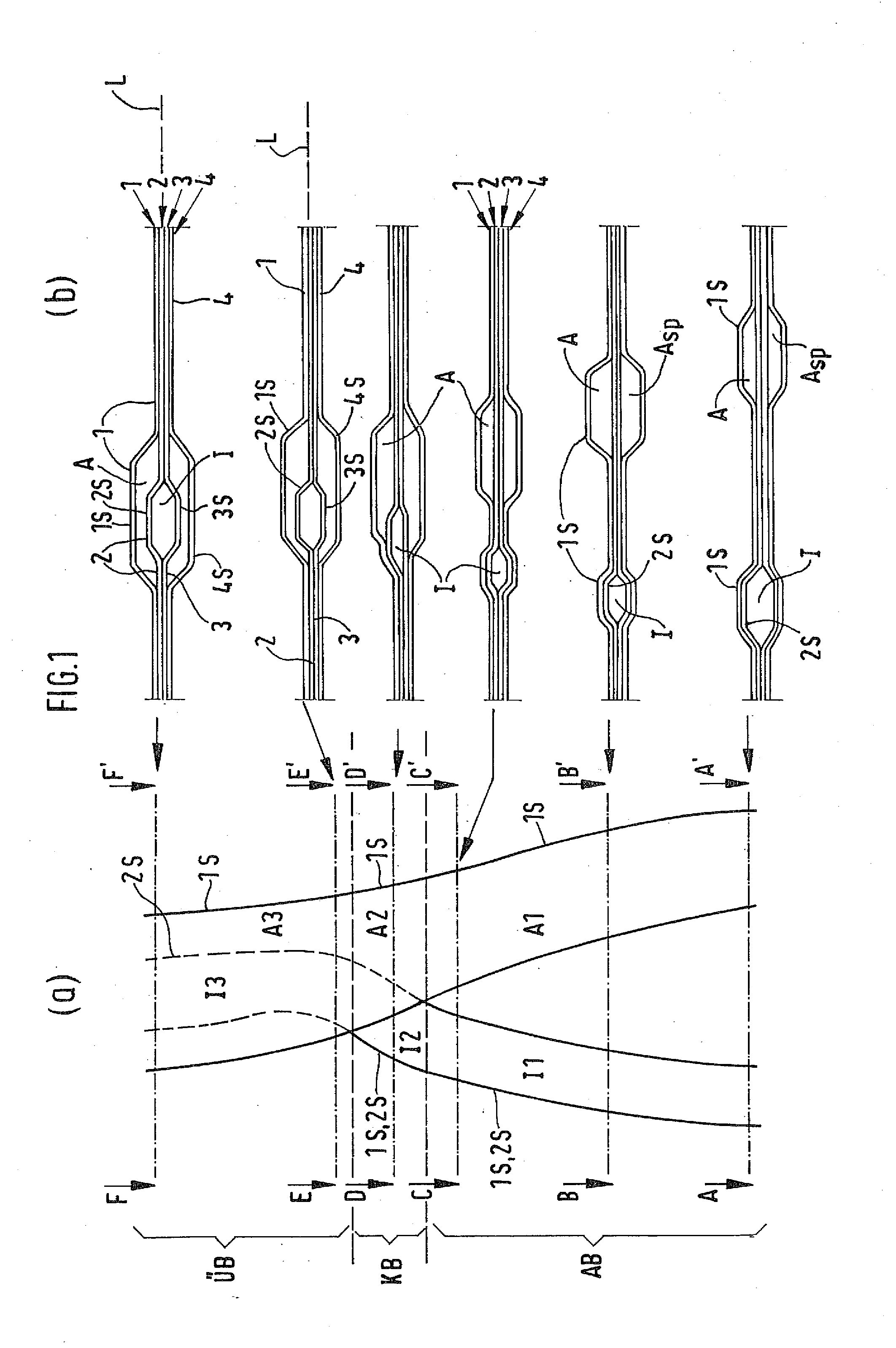
[0026]FIG. 1 a first fluid distribution element according to the invention in a view on the layer plane L (FIG. 1a) and in sectional view perpendicular to the layer plane L (FIG. 1b).

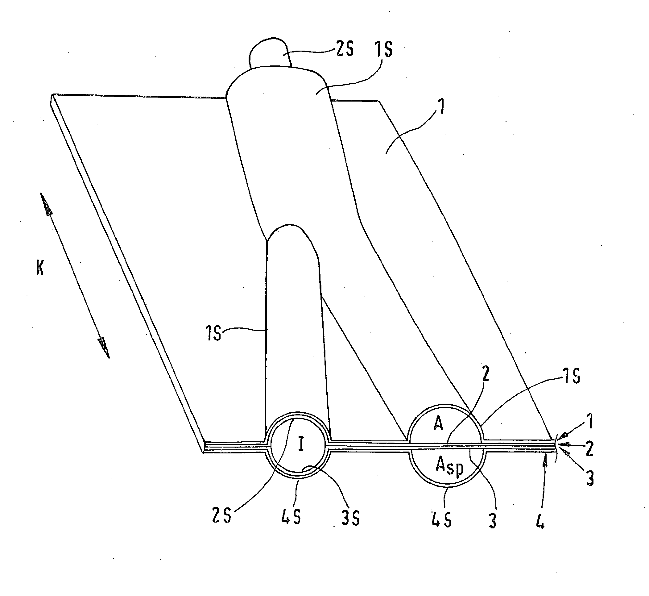
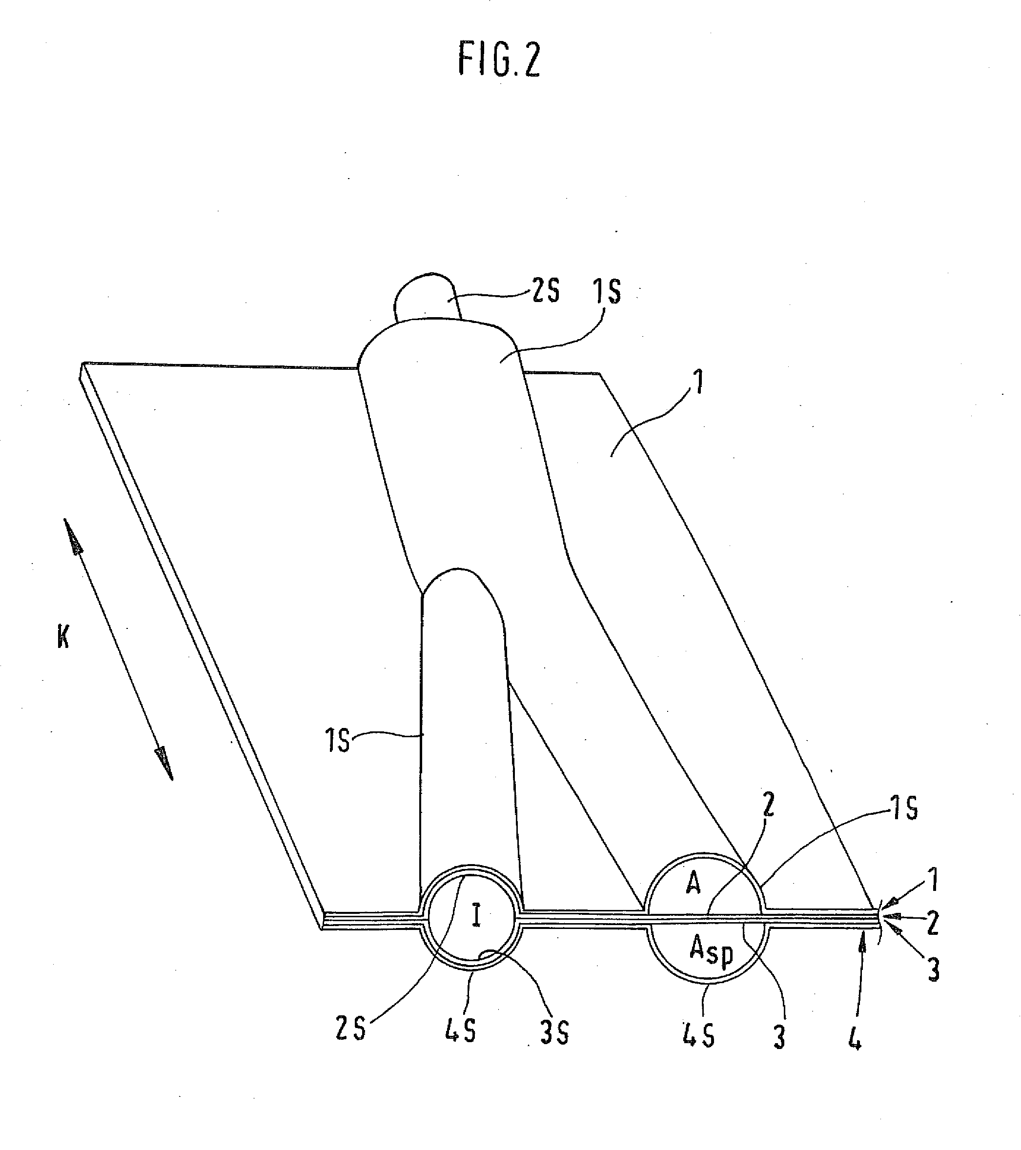
[0027]FIG. 2 an isometric view of the fluid distribution element according to the invention represented in FIG. 1.

[0028]FIG. 3 a second fluid distribution element according to the invention which is constructed analogously to the one shown in FIG. 1, however forming a branched inner channel.

[0029]FIG. 4 an arrangement of a plurality of fluid distribution elements according to the invention stacked one above the other.

[0030]FIG. 5 a Y-shaped fluid distribution part which can be connected to a fluid distribution element according to the invention.

[0031]FIG. 1 shows an embodiment of a fluid distribution element according to the invention. FIG. 1a shows a view on the layer plane L of the fluid distribution element, FIG. 1b shows different sectional views perpendicular to the layer plan...


PUM

PropertyMeasurementUnit
permeableaaaaaaaaaa
surface structureaaaaaaaaaa
pressureaaaaaaaaaa

Abstract

The fluid distribution element according to the invention has a very low spatial requirement and simplifies the interlinked connection of multichannel pipes for the purpose of construction of a compact assembly for heat exchange. In particular the fluid distribution element according to the invention can be produced in a constructionally simple manner thus without, as in the state of the art, an increased risk of leakage arising at the interpenetration points. In order to prevent in addition possible pressure losses, the construction of the fluid-conducting device can be effected advantageously by means of the fluid distribution elements such that bionic attachments are followed in the line of the channel.

Description

PRIORITY INFORMATION[0001]This application is a continuation of PCT Application No. PCT / EP2008 / 009985 filed on Nov. 25, 2008, that claims priority to German Application No. 102007056995.7, filed on Nov. 27, 2007. Both applications are incorporated herein by reference in their entireties.BACKGROUND OF THE INVENTION[0002]The present invention relates to a fluid distribution element for fluid-conducting devices, in particular for devices which have multichannel pipes. The fluid distribution element according to the invention is described subsequently alternatively also as distributor coupling, fluid distribution device or fluid collection device. Furthermore, the present invention relates to an arrangement comprising such fluid distribution elements and also to production methods for producing such fluid distribution elements.[0003]Fluid distribution elements are of interest in particular if heat- or material transport between a plurality of carriers (fluids) is intended to take place ...

Claims


Application Information

Patent Timeline
Patent Type & Authority Applications(United States)
IPC IPC(8): F15D1/02B23K20/04
CPCF28F3/14F28D9/0037Y10T137/8593
Inventor SICRE, BENOITOLTERSDORF, THOREHERMAN, MICHAEL
Owner FRAUNHOFER GESELLSCHAFT ZUR FOERDERUNG DER ANGEWANDTEN FORSCHUNG EV
Why Eureka
Try Eureka