
Controlled weld pool volume control of welding processes

a control technology for welding processes and weld pools, applied in the field of constant weld pool volume control of welding processes, can solve the problems of inability to precisely control the volume of the weld pool to reliably produce quality welds or weld profiles, and the present process is not able to provide the control of the size and shape so as to improve the process control of the volume of the weld pool and the accuracy of volume estimation

Active Publication Date: 2010-11-18
SIGMA LAB OF ARIZONA
View PDF11 Cites 47 Cited by
  • Summary
  • Abstract
  • Description
  • Claims
  • Application Information

AI Technical Summary

Benefits of technology

The present invention provides a method for controlling the size and shape of the weld pool in welding processes by using thermal sensors and a thermal inverse model. This allows for direct control of the weld pool volume, resulting in better process control and more accurate volume estimation. The method can be used with various arc welding processes and beam welding processes, and can also be used for material deposition and build-up processes involving arc or beam welding as the heat source. The invention provides a way to monitor and control welding processes in real-time, resulting in improved efficiency and accuracy.

Problems solved by technology

However, welding processes are still unable to be precisely controlled to reliably produce quality welds or weld profiles.
However, in general, there is not at present a direct method for sensing the volume of the weld pool and an associated control scheme that directly regulates the volume of the weld pool.
However, none of the present processes are able to provide the control of the size and shape of the weld pool that is desired for some applications.

Method used


Image

  • Controlled weld pool volume control of welding processes
  • Controlled weld pool volume control of welding processes
  • Controlled weld pool volume control of welding processes

Examples


Embodiment Construction

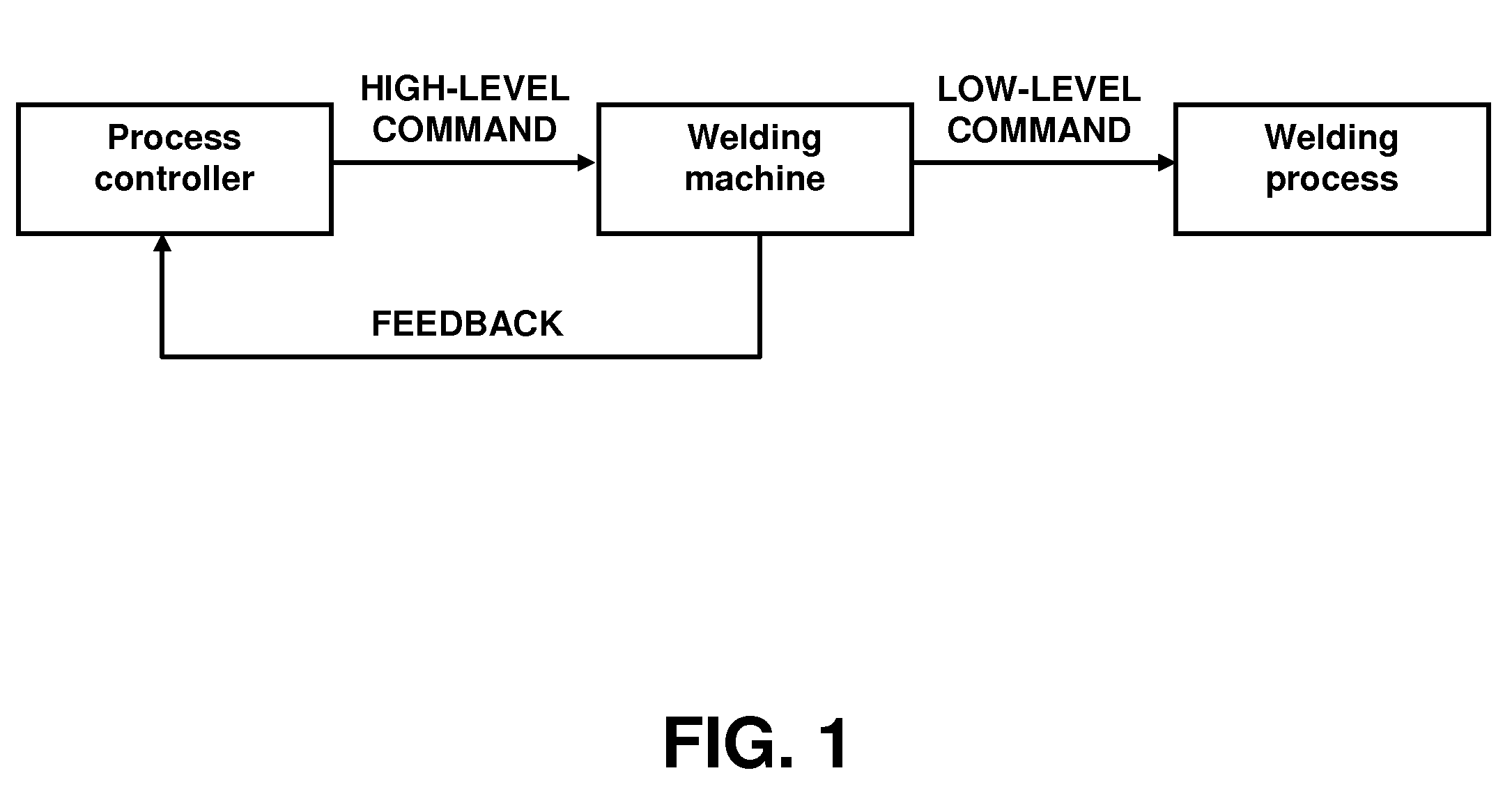
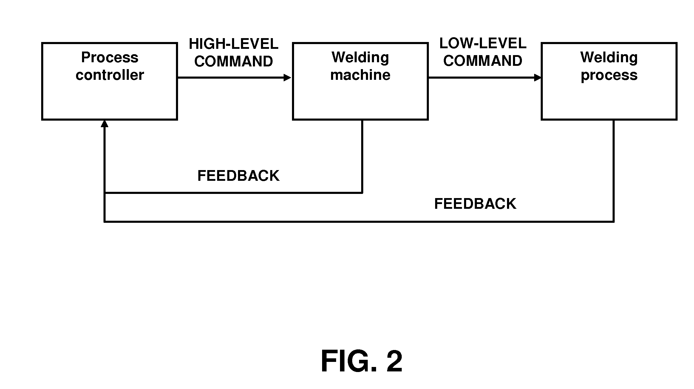
[0024]Embodiments of the present invention provide a method of process control for fusion welding in general, such as control of a fusion welding process by maintaining a controlled (e.g., substantially constant) weld pool size or volume. Embodiments of the invention provide a method of linking machine and process variables to the weld pool size or volume in real time or near real time and thereby enable controlled weld pool volume control. Embodiments of the present invention can further comprise a method of using thermal inverse models to rapidly process real-time data and enable models-based control of welding processes so as to implement controlled weld pool volume control. In the description below, the example of a constant weld pool volume will be used for simplicity of illustration, although the invention can also be used to control weld pool volume to conform to other desired volume characteristics such as linear change, or change based on portion of a weld or materials invo...


PUM

PropertyMeasurementUnit
volumeaaaaaaaaaa
thermalaaaaaaaaaa
thermal inverse modelaaaaaaaaaa

Abstract

A new method of process control for fusion welding maintains a controlled weld pool size or volume, for example in some applications a substantially constant weld pool size or volume. The invention comprises a method of linking machine and process variables to the weld pool size or volume in real time, thereby enabling constant weld pool volume control. The invention further comprises a method of using thermal inverse models to rapidly process real-time data and enable models-based control of welding processes so as to implement constant weld pool volume control.

Description

RELATED APPLICATIONS[0001]This invention is claims priority to U.S. provisional 61 / 178,473, filed May 14, 2009, which is incorporated herein by reference.FIELD OF THE INVENTION[0002]This invention relates to welding processes and, in particular, to a method and apparatus for constant weld pool volume control of a welding process.BACKGROUND OF THE INVENTION[0003]Welding processes are routinely used for joining pieces of metal in the manufacturing and construction industries, including the aerospace, automotive, and electronics industries. These welding processes typically use electric arcs or energy beams as heat sources. However, welding processes are still unable to be precisely controlled to reliably produce quality welds or weld profiles. In many applications, a higher level of process control is required and, as such, feedback from the process can be vital to properly regulate welding conditions so that the desired process control can be achieved.[0004]Currently, such process co...

Claims


Application Information

Patent Timeline
Patent Type & Authority Applications(United States)
IPC IPC(8): B23K9/18B23K26/00B23K9/16B23K9/04B23K15/00
CPCB23K9/0953B23K9/0956B23K9/32B23K15/0046B23K31/00B23K26/03B23K26/032B23K26/034B23K26/20B23K15/02B23K26/21
Inventor DAVE, VIVEK R.COLA, MARK J.
Owner SIGMA LAB OF ARIZONA
Learn More