
Blade seal

a technology of blades and seals, applied in the direction of aircraft components, wing adjustments, aircraft control, etc., can solve the problems of small gap in takeoff configuration, increase drag, noise and fuel consumption, and can produce several hundred kilograms of drag overall

Active Publication Date: 2010-11-18
AIRBUS OPERATIONS LTD
View PDF5 Cites 26 Cited by
  • Summary
  • Abstract
  • Description
  • Claims
  • Application Information

AI Technical Summary

Benefits of technology

[0010]This invention is advantageous in that the shape of the blade seal may be manipulated under active control of the actuator embedded therein. The blade seal is operable such that its thin edge can apply an increased sealing force against an adjacent sealing surface when the actuator is activated, so providing an improved seal.
[0012]In one embodiment, the ribbon material is a shape memory material. This may be a shape memory alloy, or a shape memory polymer. Shape memory materials assume a nominal shape at a first temperature, and can be deformed to a second desired shape when heated. When the material is cool, the shape memory material will assume its first shape, and when heated to its activation temperature, the shape memory material will assume its second shape. A property of shape memory materials is that they suffer very little fatigue and so this process of heating and cooling so as to change the shape of the shape memory material may be repeated almost indefinitely. In this way, the shape memory material may be used as an actuator. The shape memory material may be heated by radiation or Joule heating. In a preferred embodiment, a heating wire is attached to the shape memory ribbon such that the shape memory ribbon changes shape when the heating wire is energised.

Problems solved by technology

However, during takeoff whilst it is desirable to deploy the slats at least partially to increase lift, it is preferable that there is no slot between the slat and the wing because this increases drag, noise and fuel consumption.
However, in practice, due to the wing span-wise curvature from the in-flight lift forces produced by the wing, a small gap exists in the takeoff configuration between the trailing edge of the slat and the D-nose profile.
This gap can produce several hundred kilograms of drag overall in the takeoff condition for a commercial airliner.
This gap can reduce aerodynamic performance and lead to increased drag which is undesirable when the wing 1 is in its high lift configuration with the slats 5 deployed.
However, on larger wing curvatures, especially at the mid and outboard leading edge of the wing, profiling the D-nose may cause the slats to scrape against the D-nose profile as they are retracted.

Method used


Image

  • Blade seal
  • Blade seal
  • Blade seal

Examples


Embodiment Construction

)

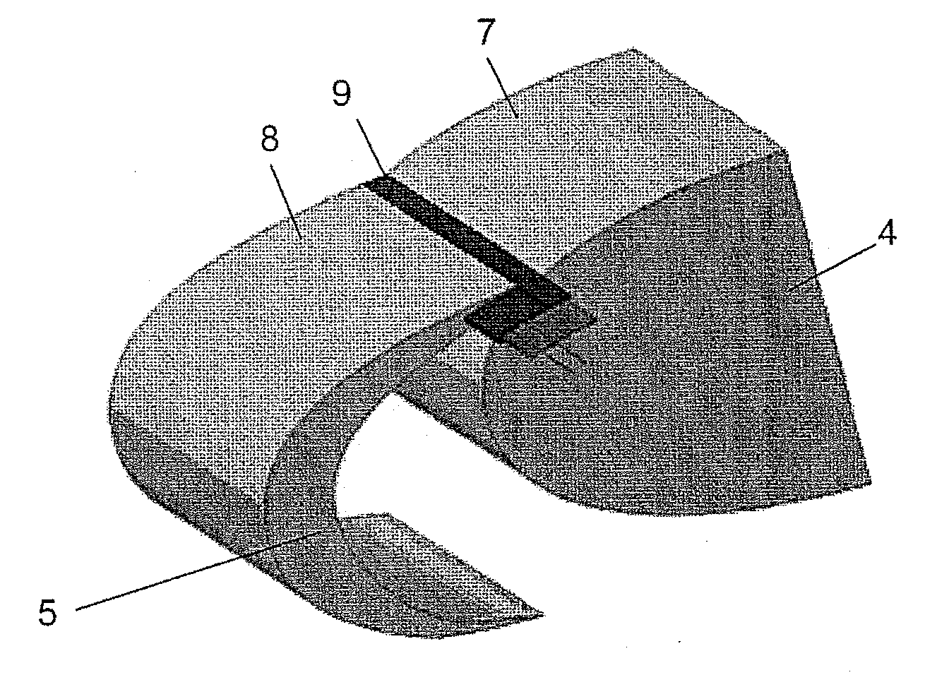
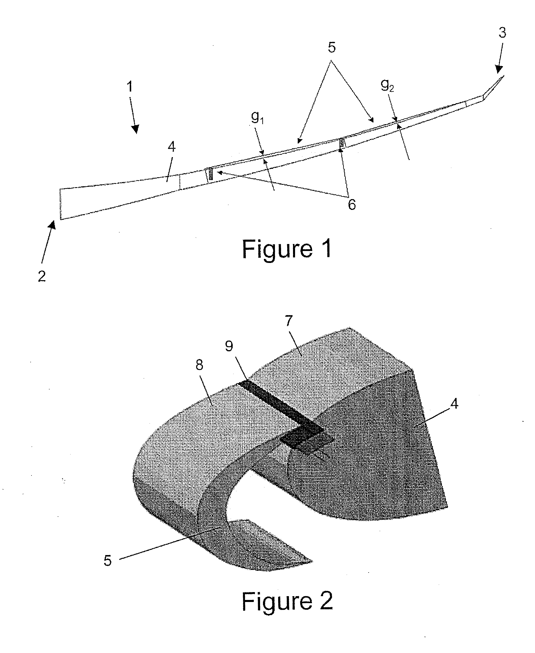
[0028]As shown in FIG. 2, the fixed aerofoil portion 4 has a D-nose panel 7 which forms the aerodynamic profile of the leading edge of the fixed wing portion 4. The slat 5 has a trailing edge 8 having a resilient blade seal 9 mounted thereto. The blade seal 9 is adapted to seal between the trailing edge 8 of the slat 5 and the D-nose panel 7 of the fixed aerofoil portion 4 as the slat moves between its retracted and extended positions. The slat 5 is shown in its extended position in FIG. 2.

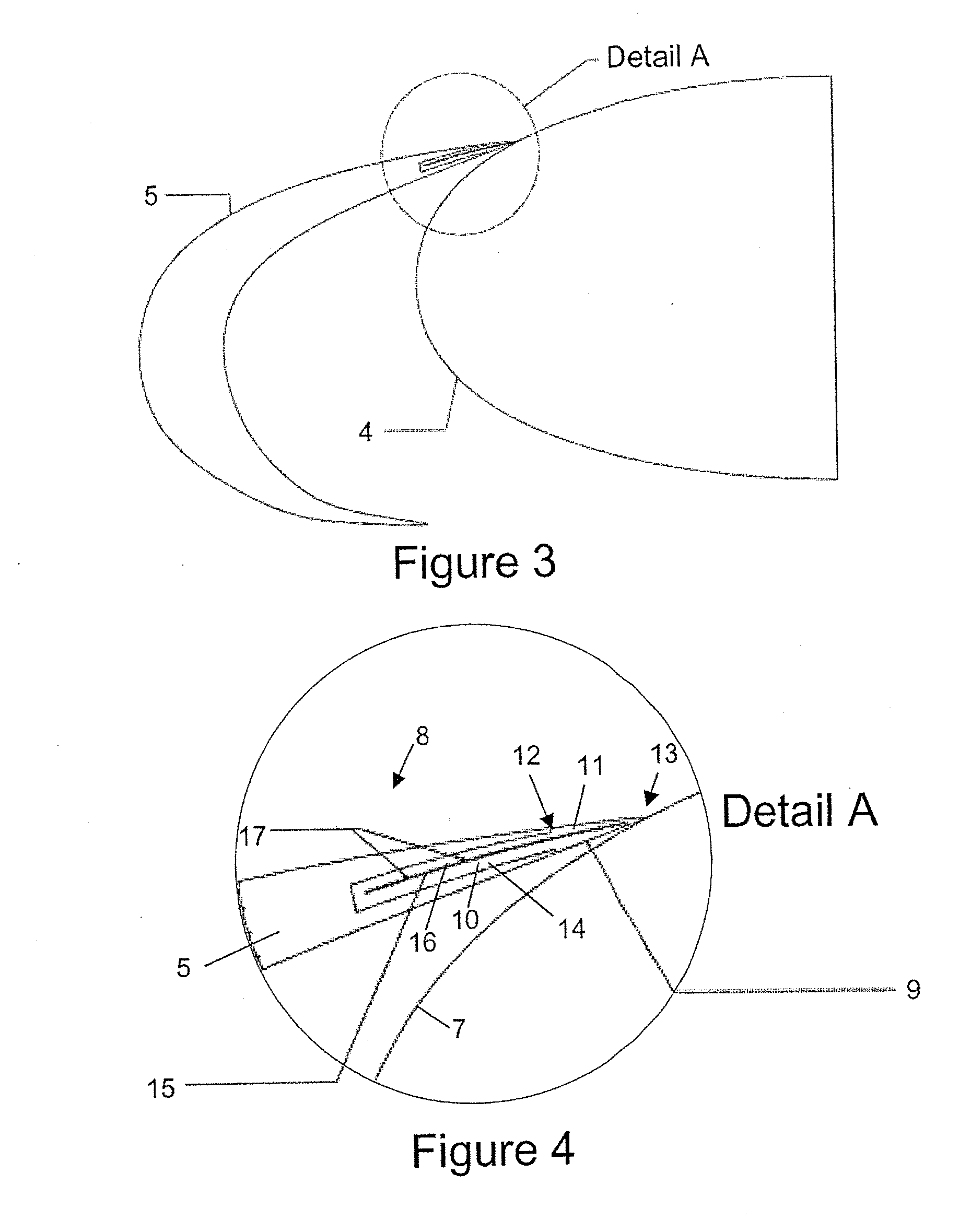
[0029]FIG. 3 shows a schematic cross section view through the leading edge of the fixed wing portion 4 and the slat 5. FIG. 4 shows detail A of FIG. 3 of the trailing edge 8 of the slat 5 and the engagement of the blade seal 9 with the D-nose panel 7. The blade seal 9 includes an embedded portion 10 and an exposed portion 11. The embedded portion 10 extends into the structure of the slat trailing edge 8. The exposed portion 11 extends beyond the trailing edge of the slat structure and has a gener...


PUM


Abstract

A blade seal comprises a flexible member having a relatively thick edge opposite a relatively thin edge, and an actuator at least partially embedded in the flexible member for actively deflecting the thin edge with respect to the thick edge upon activation of the actuator. The blade seal may be fixed to an aerodynamic trailing edge of either a fixed aerofoil portion or a flight control surface of an aerofoil for sealing between the fixed aerofoil portion and the flight control surface. Also, a method of sealing an aerofoil using the blade seal.

Description

FIELD OF THE INVENTION[0001]The present invention relates to a blade seal. The blade seal may be attached to an aerodynamic trailing edge of an aerofoil. The present invention also relates to a method of sealing an aerofoil using a blade seal.BACKGROUND OF THE INVENTION[0002]Slats are devices on the leading edge of an aircraft wing which are deployed during takeoff and landing to increase the lift of the wing. During landing it is desirable for the slats to be fully deployed for maximum lift. Also, during landing it is desirable to open up a small slot between the slat and the wing fixed leading edge allowing a small amount of high pressure air from the lower surface to reach the upper surface, where it helps postpone the stall. However, during takeoff whilst it is desirable to deploy the slats at least partially to increase lift, it is preferable that there is no slot between the slat and the wing because this increases drag, noise and fuel consumption.[0003]A so called “sealed sla...

Claims


Application Information

Patent Timeline
Patent Type & Authority Applications(United States)
IPC IPC(8): B64C3/50
CPCB64C7/00Y02T50/32B64C9/02Y02T50/30
Inventor COCONNIER, CHRISTOPHER
Owner AIRBUS OPERATIONS LTD
Learn More