Thin film bio valve device and its controlling apparatus

a technology of bio valves and thin films, which is applied in the direction of valve operating means/release devices, glassware laboratories, instruments, etc., can solve the problems of inability to accurately control the amount of fluid, difficult formation of thin film devices including such valves, and complex design of valves

Active Publication Date: 2010-11-18
PRECISIONBIOSENSOR INC
View PDF2 Cites 22 Cited by
  • Summary
  • Abstract
  • Description
  • Claims
  • Application Information

AI Technical Summary

Benefits of technology

[0081]A thin film bio valve device and an apparatus for controlling the thin film bio valve according to embodiments of the inventive concept may be effectively used in a va

Problems solved by technology

However, designing valves are complex and thus forming thin-film devices including such valves is difficult.
However, for these devices, it is difficult to manufacture valves having a thin film structure and thus, the amount of the fluid cannot be accurately controlled.
However, to obtain sufficient magnetic force to move the cylinder or plunger, a suitably sized ferrite core and many coils to be wound thereon are needed, and a large

Method used


Image

  • Thin film bio valve device and its controlling apparatus
  • Thin film bio valve device and its controlling apparatus
  • Thin film bio valve device and its controlling apparatus

Examples


Embodiment Construction

Technical Problem

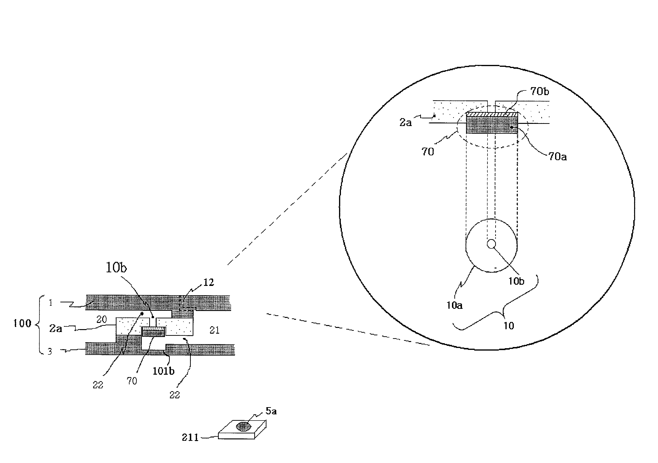
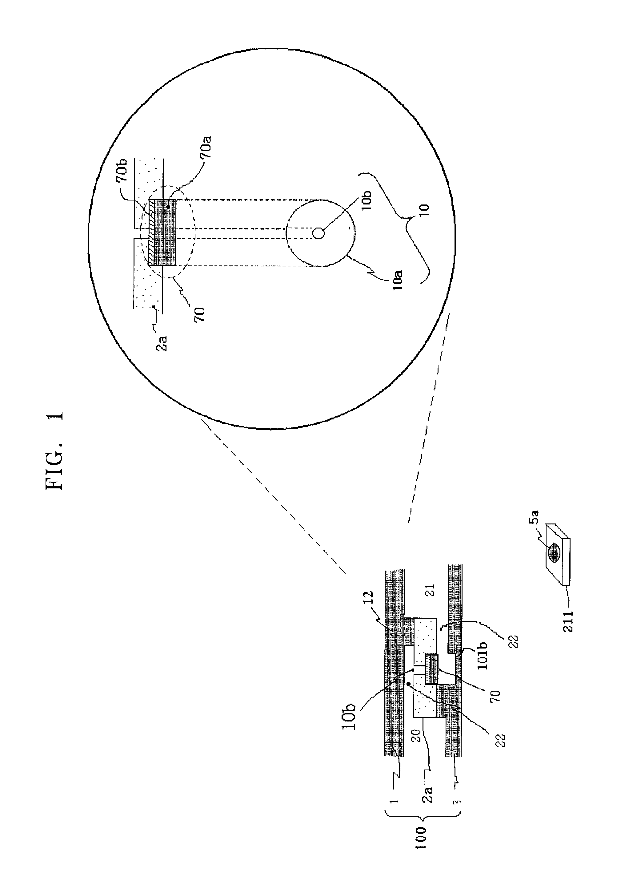
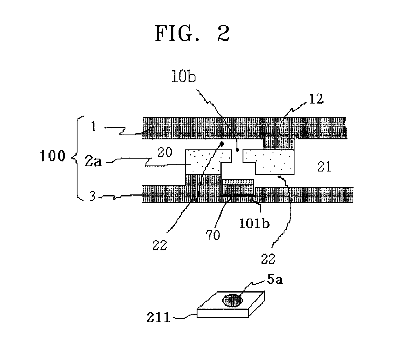
[0015]The inventive concept provides a thin film bio valve device and an apparatus for controlling the same. The thin film bio valve device only uses a permanent magnet that generates a magnetic force to open or close a channel hole without generation of heat. In the thin film bio valve device, a magnetic valve that is moved due to a magnetic force formed between a fixed top permanent magnet disposed above the channel hole or an intermediate substrate formed of a ferromagnetic material and a movable permanent magnet disposed under the body is disposed to open or close the channel hole.

Technical Solution

[0016]According to an aspect of the inventive concept, there is provided a thin film bio valve device in which a channel and a channel hole are formed between neighboring chambers in a body, a top permanent magnet is fixed and disposed above the channel hole, and a movable permanent magnet is disposed under the body and at the same time a magnetic valve is disposed wi...


PUM

PropertyMeasurementUnit
Poweraaaaaaaaaa
Electrical resistanceaaaaaaaaaa
Radiusaaaaaaaaaa

Abstract

A thin film bio valve device and an apparatus for controlling the thin film bio valve device are effectively applied in a valve structure of a thin film device, such as a lab-on-a-chip, a protein chip, or a DNA chip, for diagnosing and/or detecting a small amount of material in a fluid.

Description

TECHNICAL FIELD[0001]The inventive concept relates to a control of the flow and / or amount of a fluid in an assay device for diagnosing and / or detecting a small amount of a biomaterial included in a fluid.[0002]More particularly, the inventive concept relates to a thin film bio valve device for controlling the flow and / or amount of a fluid and an apparatus for controlling the thin film bio valve device. The thin film bio valve device includes a channel hole and the channel hole is closed or opened by using various methods. For example, a body of the thin film bio valve device includes a magnetic valve that moves due to a magnetic force formed between a fixed top permanent magnet disposed above a channel hole and a movable permanent magnet disposed under the channel hole and thus, when the magnetic valve moves in a clockwise or counter-clockwise direction, the channel hole is opened or closed.[0003]In another example, a body of the thin film bio valve device includes a magnetic valve ...

Claims


Application Information

Patent Timeline
IPC IPC(8): F16K31/08
CPCB01L3/502715Y10T436/2575B01L2300/0803B01L2300/0806B01L2300/0867B01L2400/0409B01L2400/0633B01L2400/065F16K99/0001F16K99/0011F16K99/0046F16K99/0063F16K2099/008F16K2099/0084G01N35/1097G01N2035/00247G01N2035/1034B01L3/502738
Inventor YOO, JAE CHERN
Owner PRECISIONBIOSENSOR INC
Why Eureka
Try Eureka