Energy efficient decorative lighting

a technology of decorative lighting and energy saving, applied in the direction of electroluminescent light sources, semiconductor devices of light sources, lighting and heating apparatus, etc., can solve the problems of significant amount of energy consumption and heat generation, and achieve the effects of low cost manufacturing, energy saving and energy saving

Inactive Publication Date: 2010-11-18
WILLIS ELECTRIC
View PDF91 Cites 31 Cited by
  • Summary
  • Abstract
  • Description
  • Claims
  • Application Information

AI Technical Summary

Benefits of technology

[0019]Energy efficient system for lighting is provided that allows variation of length, density of illumination and positioning. The inventive system is particularly suitable for decorative lighting and seasonal display. The lighting system comprises at least one light string having a plurality of light emitting diodes (LEDS) interconnected to a parallel set of power wires maintaining output voltage within a prescribed range. A direct current (DC) transformer is connected to the parallel set of power wires to convert alternating current (AC) input to DC output to control power to the lighting system at relatively low voltage level and less than about fifteen watts. Multiple LED light strings may be connected to the parallel set of power wires to provide decorative lighting displays of desired length, configuration and density of illumination. Accordingly, the unique system provides decorative lighting that is energy efficient and suitable for low cost manufacture compared with conventional incandescent light strings.

Problems solved by technology

Collectively, they consume significant amounts of energy and produce significant amounts of heat.

Method used


Image

  • Energy efficient decorative lighting
  • Energy efficient decorative lighting
  • Energy efficient decorative lighting

Examples


Embodiment Construction

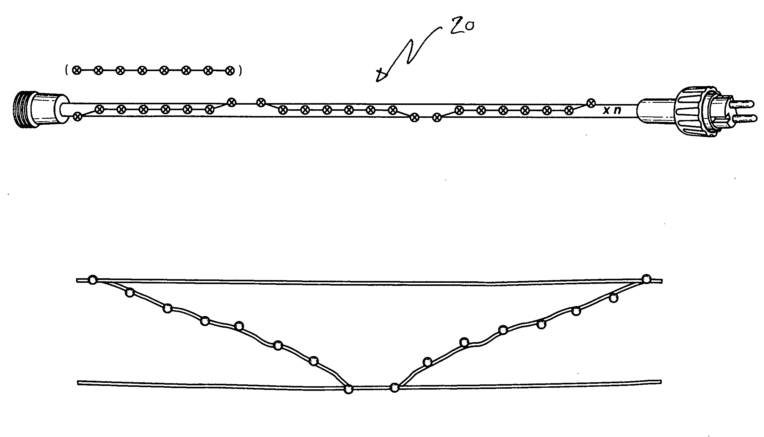
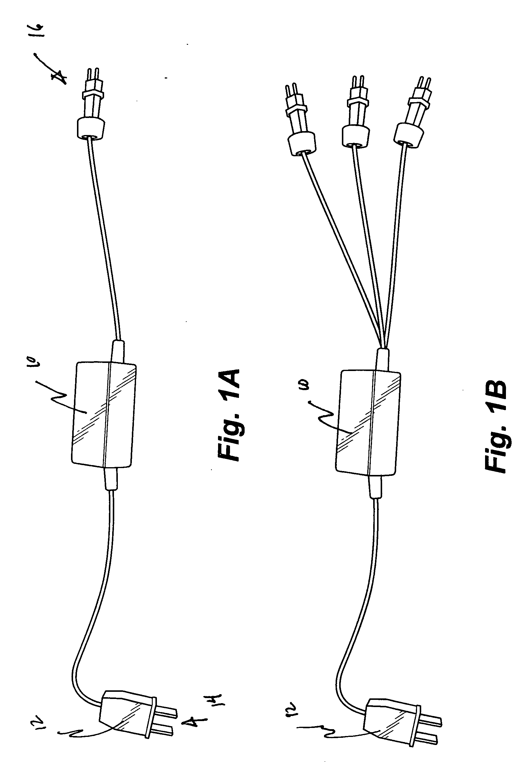
[0034]Energy efficient system for lighting is provided that allows variation of length, density of illumination and positioning. The inventive system is particularly suitable for decorative lighting and seasonal display. The lighting system comprises at least one light string having a plurality of light emitting diodes (LEDS) interconnected to a parallel set of power wires maintaining output voltage within a prescribed range. A direct current (DC) transformer is connected to the parallel set of power wires to convert alternating current (AC) input to DC output to control power to the lighting system at relatively low voltage level and less than about fifteen watts. Multiple LED light strings may be connected to the parallel set of power wires to provide decorative lighting displays of desired length, configuration and density of illumination. Accordingly, the unique system provides decorative lighting that is energy efficient and suitable for low cost manufacture compared with conve...


PUM


Abstract

Energy efficient system for lighting is provided that allows variation of length, density of illumination and positioning. The inventive system is particularly suitable for decorative lighting and seasonal display. The lighting system comprises at least one light string having a plurality of light emitting diodes (LEDS) interconnected to a parallel set of power wires maintaining output voltage within a prescribed range. A direct current (DC) transformer is connected to the parallel set of power wires to convert alternating current (AC) input to DC output to control power to the lighting system at relatively low voltage level and less than about fifteen watts. Multiple LED light strings may be connected to the parallel set of power wires to provide decorative lighting displays of desired length, configuration and density of illumination. Accordingly, the unique system provides decorative lighting that is energy efficient and suitable for low cost manufacture compared with conventional incandescent light strings.

Description

BACKGROUND OF THE INVENTION[0001]The present invention relates to decorative lighting systems, and more particularly to light string circuits including a transformer for conversion of electricity from AC to DC providing prescribed voltages to power multiple LED light sets.[0002]Decorative lighting for temporary and seasonal displays has typically been centered around the use of multiple incandescent light bulbs, such as Christmas Tree lighting. Generally, such conventional lighting is composed of relatively long strings of insulated copper wire carrying multiple lamp bases, lamp holders and incandescent light bulbs. These light strings are usually provided with a plug that is powered by AC household current. As consumers have become much more conscious of the need to conserve energy and to ensure the lighting provides a safe display, those skilled in the art have sought alternative ways to accomplish these goals.[0003]In this respect, light emitting diodes (LEDs) have gained popular...

Claims


Application Information

Patent Timeline
Patent Type & Authority Applications(United States)
IPC IPC(8): H05B37/02
CPCH05B33/0803H05B45/345F21S4/10F21V23/02F21Y2115/10
Inventor CHEN, JOHNNY
Owner WILLIS ELECTRIC
Why Eureka
Try Eureka