Receiver With Enhanced Clock And Data Recovery

Active Publication Date: 2010-11-18
RAMBUS INC
View PDF45 Cites 44 Cited by
  • Summary
  • Abstract
  • Description
  • Claims
  • Application Information

AI Technical Summary

Problems solved by technology

The performance of conventional digital systems is limited by

Method used


Image

  • Receiver With Enhanced Clock And Data Recovery
  • Receiver With Enhanced Clock And Data Recovery
  • Receiver With Enhanced Clock And Data Recovery

Examples


Embodiment Construction

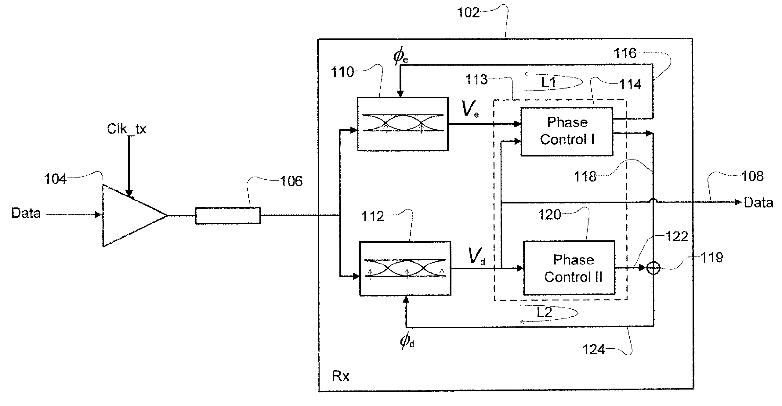
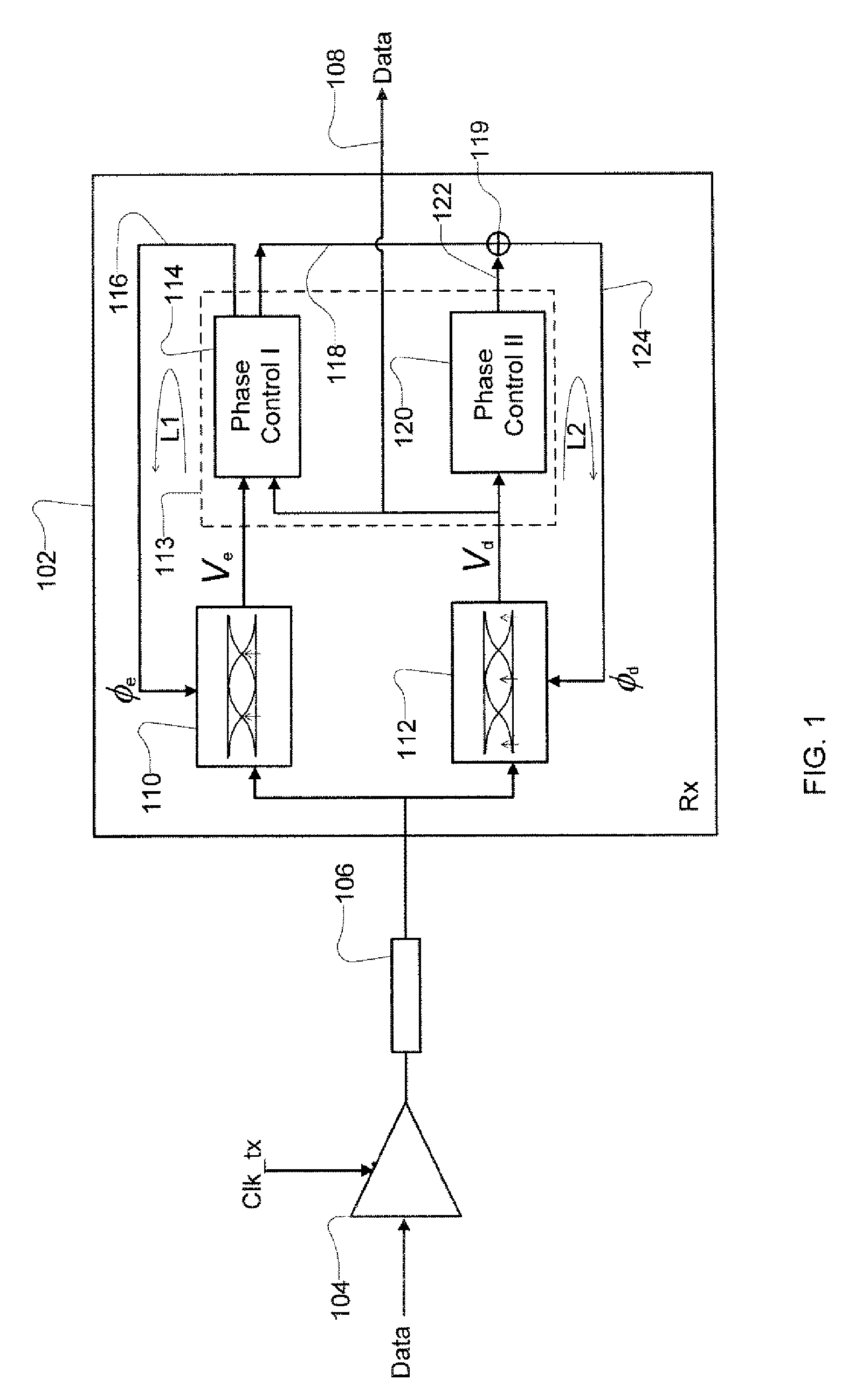
[0009]A receiver 102, such as the enhanced clock and data recovery receiver according to one embodiment of the present technology is illustrated in a data system of FIG. 1. The data system will typically include at least one transmitter 104. Transmitter 104 transmits data onto the signal path of a channel 106. Transmission of data is regulated by a transmit clock signal (shown as “Clk_tx” in FIG. 1) that is coupled with the transmitter 104. Signal path of the channel 106 may be a single ended signal path or differential signal paths, for example. Thus, the transmitter may be a differential signal transmitter or a single ended signal transmitter. Data signal 108 is a digital signal produced from the signal of the channel 106 and represents the recovered data that was transmitted from the transmitter 104.

[0010]In the embodiment of FIG. 1, the receiver 102 typically includes edge sampler 110, data sampler 112, and one or more clock and data recovery elements 113. In the present embodim...


PUM


Abstract

A receiver device implements enhanced data reception with edge-based clock and data recovery such as with a flash analog-to-digital converter architecture. In an example embodiment, the device implements a first phase adjustment control loop, with for example, a bang-bang phase detector, that detects data transitions for adjusting sampling at an optimal edge time with an edge sampler by adjusting a phase of an edge clock of the sampler. This loop may further adjust sampling in received data intervals for optimal data reception by adjusting the phase of a data clock of a data sampler such a flash ADC. The device may also implement a second phase adjustment control loop with, for example, a baud-rate phase detector, that detects data intervals for further adjusting sampling at an optimal data time with the data sampler.

Description

CROSS-REFERENCE TO RELATED APPLICATIONS[0001]The present application claims the benefit of Application Ser. No. 61 / 063,264, filed Feb. 1, 2008, entitled RECEIVER WITH ENHANCED CLOCK AND DATA RECOVERY, the disclosure of which is hereby incorporated herein by reference.BACKGROUND ART[0002]The performance of conventional digital systems is limited by the transmission interconnection between integrated circuits. In such systems, a transmitter sends data onto a channel by setting a signal parameter of an output signal, such as current or voltage, to one of a plurality of discrete values during each of a succession of intervals referred to herein as data intervals. The data intervals are regulated by a transmitter clock. The data is in turn received by a receiver on the channel. The receiving IC device needs to recognize the discrete values set by the transmitter in the data intervals so it may be used in the receiving IC device. To do so, a receiving device will typically utilize a clock...

Claims


Application Information

Patent Timeline
IPC IPC(8): H03L7/06
CPCH04L2027/0067H04L7/033H04L2025/0349H04L2027/004H04L7/0004H04L25/062H04L2027/0069H04L7/0062G06Q10/06312G06Q10/103H04L7/0334H04L7/0016H04L7/0331
Inventor LEE, HAE-CHANGLEIBOWITZ, BRIANKIM, JAEHASAVOJ, JAFAR
Owner RAMBUS INC
Why Eureka
Try Eureka