Digital performance monitoring for an optical communications system

a technology of optical communication system and digital performance monitoring, applied in the direction of transmission monitoring, transmission monitoring/testing/fault measurement system, electrical equipment, etc., can solve the problems of degrading the accuracy of any performance parameters calculated at the monitoring point, the importance of monitoring and management of the network, and the restriction of conventional optical signal and spectrum analysis equipment to laboratory use. , to achieve the effect of high-quality correlation of sample data

Active Publication Date: 2008-04-08
CIENA
View PDF14 Cites 36 Cited by
  • Summary
  • Abstract
  • Description
  • Claims
  • Application Information

AI Technical Summary

Benefits of technology

[0014]In some embodiments, the storage of samples (and possibly corrected data bits) by each one of a plurality of parallel channel monitors is controlled such that the storage operation occurs si...

Problems solved by technology

As the traffic on fiber optic networks increases, monitoring and management of the networks become increasingly important issues.
Due to their cost and complexity, conventional optical signal and spectrum analysis equipment is typically restricted to laboratory use.
While the above-described systems enable some degree of performance monitoring, they tend to suffer a number of disadvantages.
Any error between the design and actual parameter va...

Method used


Image

  • Digital performance monitoring for an optical communications system
  • Digital performance monitoring for an optical communications system
  • Digital performance monitoring for an optical communications system

Examples


first embodiment

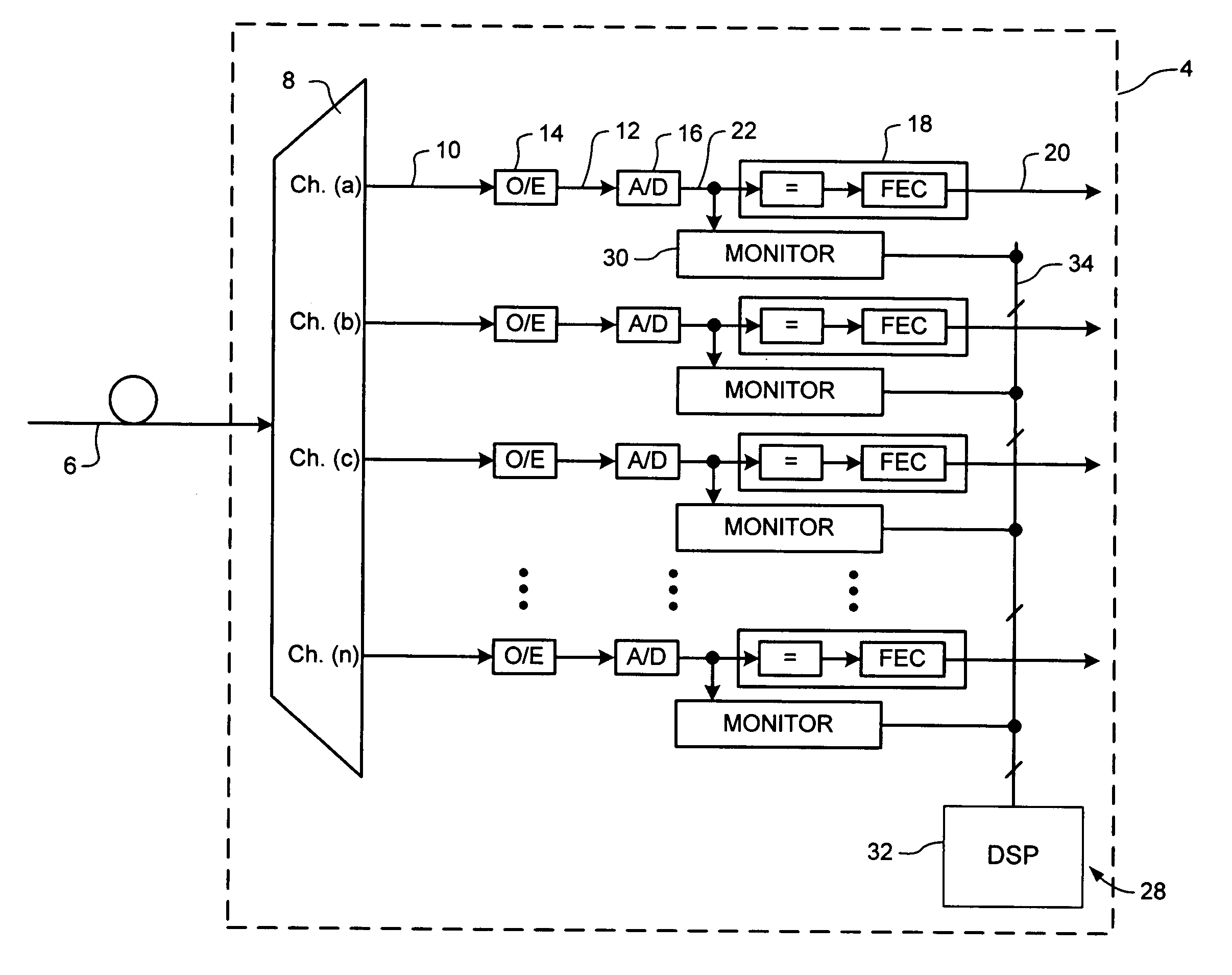
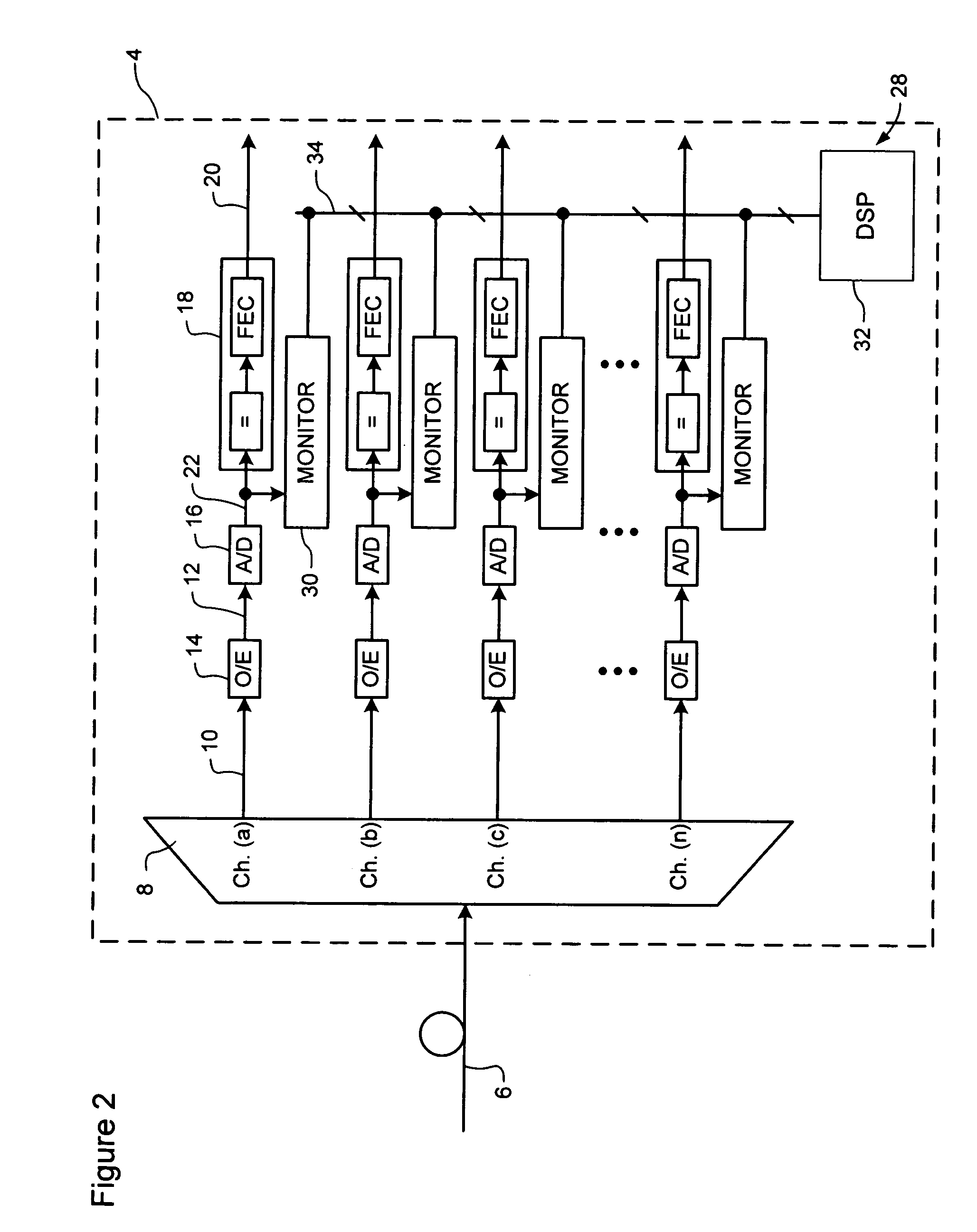
[0032]As may be appreciated, the architecture of the performance monitoring system 28 is substantially independent of the channel plan of the optical communications system 2. In particular, each channel monitor 30 is substantially identical, and operates independently of the other channel monitors 30. Sample data stored by each channel monitor 30 is transferred to the DSP 32 (e.g. under control of the DSP 32) which performs desired signal processing and analysis steps. Consequently, changes in the channel plan can readily be accommodated. The design and implementation of a suitable DSP 32 and data bus 34 structure capable of facilitating communication between the DSP 32 and a very large number of channel monitors 30 is well within the purview of those of ordinary skill in the art. Because each channel monitor 30 operates independently, the performance monitor system 28 is substantially insensitive to the wavelength separation between adjacent channels. Thus it will be appreciated th...

second embodiment

[0039]FIG. 4 is a block diagram showing the channel monitor 30, which also includes a data memory 44 (which may also be provided as a conventional RAM) for storing sequential bits of the recovered digital data stream generated by the decoder circuit 18. The storage of both sample data 22 and recovered digital data 20 is preferable, in that it greatly increases the range of analysis that can be performed by the DSP 32, without an undue increase in cost or complexity. As with the A / D converter 16, the channel monitor 30 exploits a “dual use” for the decoder circuit 18 already present as part of the data path of the network node 4, and thereby reduces the cost of implementing the performance monitoring system 28.

[0040]In the embodiment of FIG. 4, the sample memory 36 is coupled to the A / D converter 16 as described above in order to store successive N-bit samples 32 generated by the A / D converter 16. Similarly, the data memory 44 is coupled to the output of the FEC circuit 26 in order t...

third embodiment

[0068]FIG. 7 shows the present invention, in which a mode selector 66 is controlled by the external DSP 32 to select one of the polarization modes of the channel signal 10. The In-phase and Quadrature components of the selected mode are then passed to the A / D converters 16 and decoder 18 for processing as described above with respect to FIG. 6a. In this case, the coherent optical receiver 58, mode selector 66 and A / D converters 16 cooperate to sample to complex E-field of the selected polarization mode.

[0069]The performance monitor of FIG. 7 is capable of performing all of the signal analysis and performance monitoring functions described above in connection with FIGS. 3-6. In addition, the embodiment of FIG. 7 is also capable of sequentially analyzing the performance of each of the orthogonal polarization modes of the channel signal 10. Even though both polarization modes cannot be analyzed simultaneously, comparison between the performance parameter values calculated for each pola...


PUM


Abstract

A digital performance monitoring method and system for an optical communications system utilizes a channel monitor and a digital signal processor (DSP). The channel monitor is designed to monitor a respective channel signal of the optical communications system, and includes a sample memory for storing sample data including a set of sequential N-bit (where N>1) samples generated by an Analog-to-Digital (A/D) converter at a predetermined sample rate. The digital signal processor (DSP) is designed to calculate at least one performance parameter of the optical communications system based on the stored sample data. The sample rate of the A/D converter is at least equal to a baud rate of the channel, and preferably satisfies the Nyquist criterion. Multiple A/D converters may be used parallel to sample respective orthogonal components of the channel signal. In this case, the stored sample data may be representative of the complex E-field of the channel signal.

Description

CROSS-REFERENCE TO RELATED APPLICATIONS[0001]This application is a Continuation-in-Part of U.S. patent application Ser. No. 10 / 145,035, filed May 15, 2002.TECHNICAL FIELD[0002]The present invention relates to performance monitoring systems, and in particular to a system for digital performance monitoring for an optical communications system.BACKGROUND OF THE INVENTION[0003]Optical communications networks are becoming increasingly popular for data transmission due to their high bandwidth data transmission. Typically, a digital data stream is encoded (e.g. using On-Off-Keying—OOK) to generate sequential symbols that are conveyed through a communications channel by a respective optical channel signal. At a receiving end of the communications channel, an Optical-to-Electrical (O / E) converter detects the received optical channel signal and generates a corresponding analog electrical channel signal. The O / E converter is followed by an Analog-to-Digital (A / D) converter, which generates seq...

Claims


Application Information

Patent Timeline
IPC IPC(8): H04B10/08
CPCH04B10/077H04B10/07955H04B2210/258
Inventor STRAWCZYNSKI, LEOROBERTS, KIM B.MCNICOL, JOHN
Owner CIENA
Why Eureka
Try Eureka