
Frequency synchronizer

Inactive Publication Date: 2005-09-20
THE UNITED STATES OF AMERICA AS REPRESENTED BY THE SECRETARY OF THE NAVY
View PDF5 Cites 35 Cited by
  • Summary
  • Abstract
  • Description
  • Claims
  • Application Information

AI Technical Summary

Benefits of technology

[0013]Since the frequency synchronizer of the invention operates without a transmitted preamble, the energy efficiency and the bandwidth efficiency of the communications system are greater than for systems that require preambles. An important advantage of the invention is that it obviates the need for different modulation methods for signals that employ preambles.

Problems solved by technology

Generally, the synchronizers for the older, conventional digital receivers are inadequate for the newer techniques.
However, this method of synchronization has certain undesirable characteristics.
A serious problem arises if the receiver is unable to detect the preamble, thus leading to the loss of the follow-on message.
Another potential problem of great concern when operating in the presence of an adversary is that the use of a different modulation for a preamble from that for data offers the adversary significant information useful for a jamming attack.

Method used


Image

  • Frequency synchronizer
  • Frequency synchronizer
  • Frequency synchronizer

Examples


Embodiment Construction

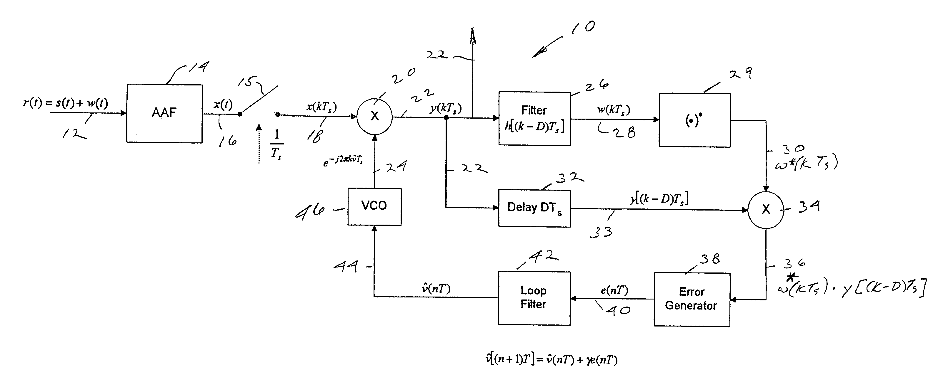
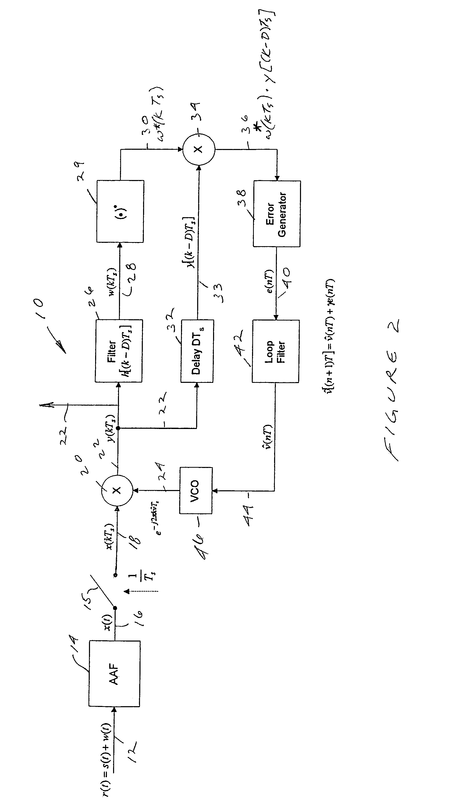
[0019]The present invention is directed to a frequency synchronizer for synchronizing to a Continuous-Phase Modulation (CPM) signal that does not require phase or timing information from a detected signal prior to processing for frequency estimation. Nor does the invention require that there be a preamble of known symbols at the beginning of a transmitted sequence. Referring to FIG. 2, there is shown a block diagram of a method for implementing a frequency synthesizer 10 that embodies several features of the present invention. A received signal 12 consisting of a CPM signal s(t) of the dual-h, 4-ary, full-response type and an additive white Gaussian noise component w(t) may be represented as a function of time t by the equation r(t)=s(t)+w(t). Signal 12 is transformed by an anti-aliasing filter 14 into a time dependent signal 16 represented by x(t). The anti-aliasing filter 14 essentially removes from signal 12 those frequency components not essential for maintaining information con...


PUM


Abstract

A frequency synchronizer system is based on the maximum likelihood criterion from estimation theory and that can achieve both frequency acquisition and frequency tracking without requiring knowledge at the receiver of the carrier's phase angle, baud timing, or a preamble consisting of known signal symbols. The synchronizer includes a processor for executing the following sequence of operations: a) initializing an estimated frequency correction factor; b) determining a corrected frequency offset value from a first product of a sample signal and the estimated frequency correction factor; c) filtering a first sample of the corrected frequency offset value to obtain a filtered corrected frequency offset value; d) imparting a delay to a second sample of the corrected frequency offset value to obtain a delayed corrected frequency offset value; e) determining a conjugate product value from a second product of the filtered corrected frequency offset value and a conjugate of the filtered corrected frequency offset value; f) determining a delay conjugate value from a third product of the delayed corrected frequency offset value and the conjugate product value; g) determining an error signal from the delay conjugate value; h) determining a frequency offset value from the error signal; and i) determining an updated value of the estimated frequency correction factor from the frequency offset value.

Description

BACKGROUND OF THE INVENTION[0001]The present invention generally relates to frequency synchronizers for digital communications systems, and more particularly, to frequency synchronizers that are based on the maximum likelihood criterion from estimation theory and that can achieve both frequency acquisition and frequency tracking without requiring knowledge at the receiver of the carrier's phase angle, baud timing, or a preamble consisting of known signal symbols.[0002]All digital communications systems operate on the basis of a finite number of possible waveforms available for transmission during any particular signaling interval. The digital receivers must process versions of these transmitted waveforms which are corrupted by noise, channel fading, multipath, distortion, unintentional interference, and jamming, for example. The receiver's task is to determine which was the transmitted waveform for a particular signaling interval. Acceptable performance requires that this determinat...

Claims


Application Information

Patent Timeline
IPC IPC(8): H04L27/06H04L27/00H04L27/227
CPCH04L27/2273H04L2027/0028H04L2027/0057H04L2027/0067
Inventor PETTIT, RAY H.
Owner THE UNITED STATES OF AMERICA AS REPRESENTED BY THE SECRETARY OF THE NAVY
Learn More