
Dual-mode vehicle rear vision system

a rear-view and dual-mode technology, applied in the field of rear-view systems, can solve the problems of adding to the cost and overall complexity of the rear-view vision system, and achieve the effect of improving occupant safety, reducing or mitigating injuries

Inactive Publication Date: 2010-11-18
FORD GLOBAL TECH LLC
View PDF13 Cites 18 Cited by
  • Summary
  • Abstract
  • Description
  • Claims
  • Application Information

AI Technical Summary

Benefits of technology

[0010]Upon detection of a collision threat or a backup hazard, the ECM directs a function change in at least one vehicle system. If a collision threat is detected the ECM may activate an occupant safety system such as a seatbelt pre-tensioner, an airbag, or an active whip-lash preventing head rest. The dual-mode rear vision system is thus able to improve occupant safety by reducing or mitigating injuries that may be caused by a rear impact.

Problems solved by technology

The need for two separate rear vision sensors adds to the cost and overall complexity of the rearward vision system.

Method used


Image

  • Dual-mode vehicle rear vision system
  • Dual-mode vehicle rear vision system
  • Dual-mode vehicle rear vision system

Examples


Embodiment Construction

[0019]By way of example, a system and method for implementing the present invention is described below. The system and methodology may be adapted, modified or rearranged to best fit a particular implementation without departing from the scope of the present invention.

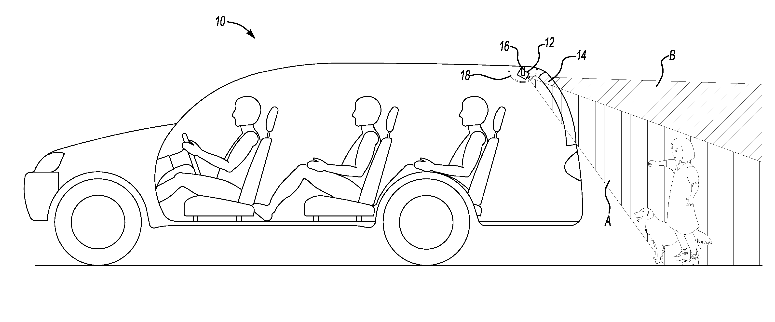
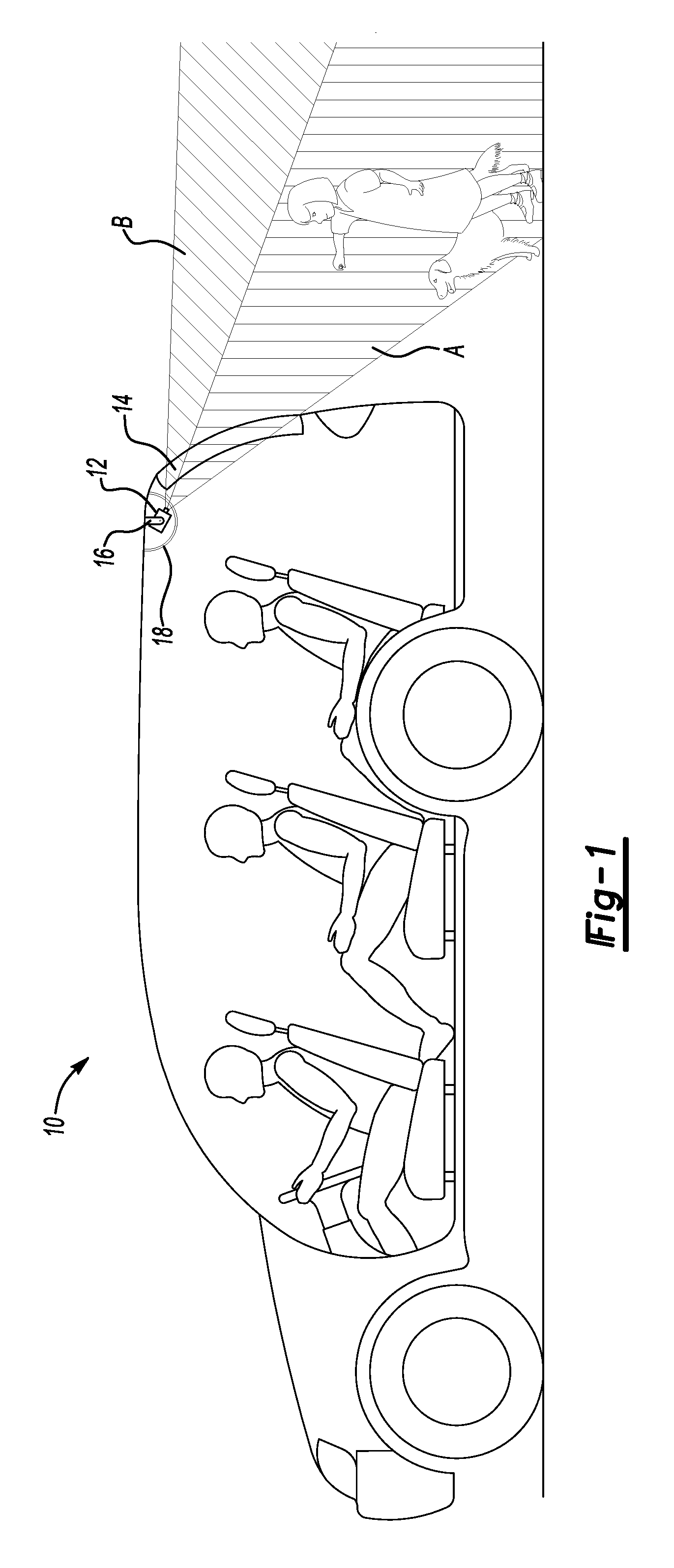
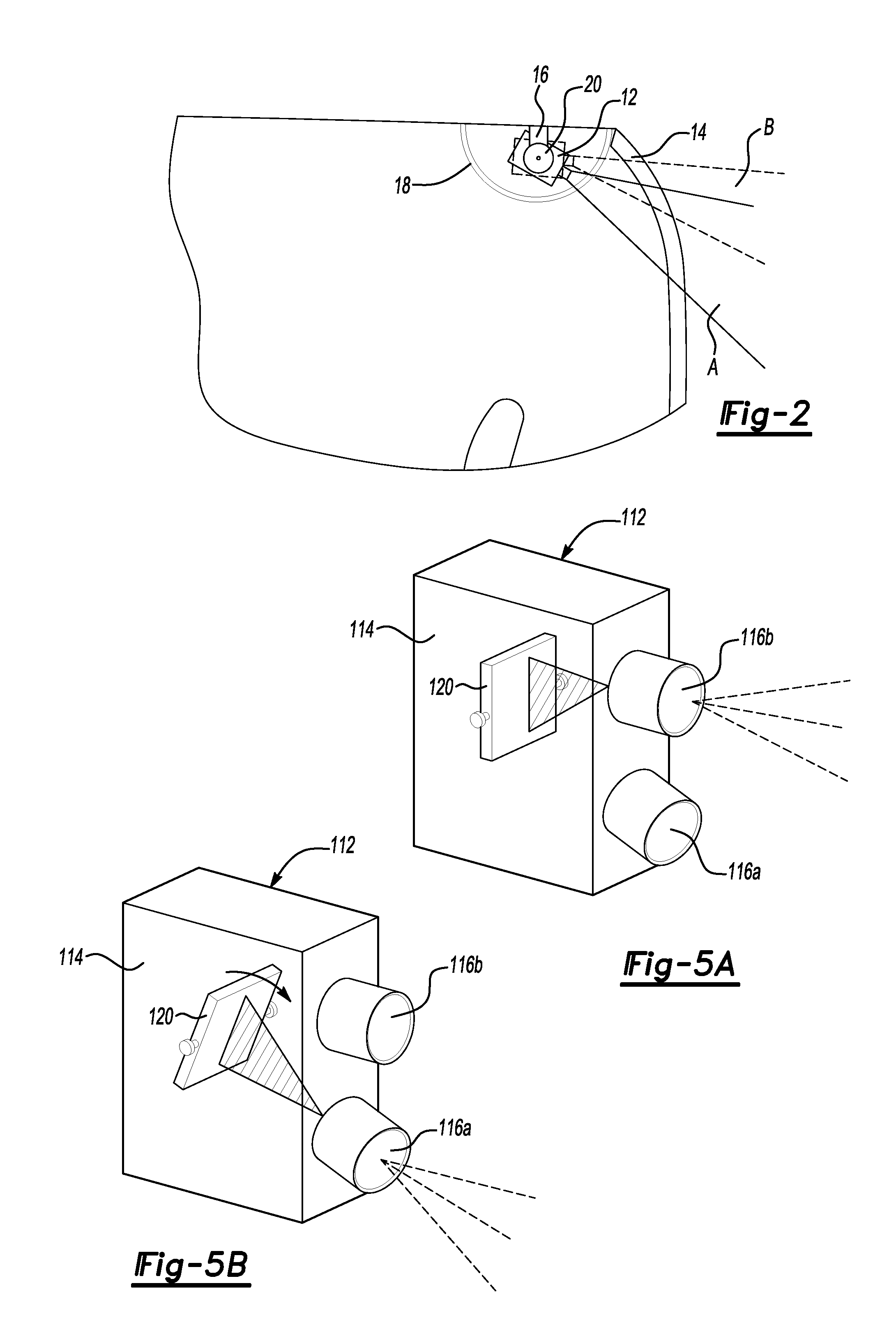
[0020]Referring to FIG. 1, a vehicle 10 is equipped with an electro-optical imaging device 12, hereafter referred to as a camera, located adjacent the upper rear portion of the passenger compartment near to the juncture between a rear window 14 and the interior of the vehicle roof. Camera 12 is retained in a movable mount 16 and preferably enclosed by a housing 18. Housing 18 may be integrated with the headliner forming the inner surface of the roof, or it may be a separate component. Camera 12 may operate in the visible, near-infrared, or any appropriate spectrum, and may employ a CCD (charge-coupled device) or CMOS (complimentary metal-oxide semiconductor) image sensor. Housing 18 may have one or more openings (not sh...


PUM


Abstract

A dual-mode rear vision system for an automotive vehicle includes an electro-optical imaging device operable in a short range mode to image a backup region immediately rearward of the vehicle and operable in a long range mode to image a collision threat region rearward of the backup region. The imaging device assumes the short range mode when the vehicle is in a reverse travel mode and assumes the long range mode when the vehicle is in a non-reverse travel mode. An electronic control module (ECM) analyzes imagery from the imaging device to detect backup hazards when in the reverse travel mode, and to detect rear collision threats when in the non-reverse travel mode. The ECM activates an occupant protection system if a collision threat is detected, and generates a driver alert and / or a braking intervention if a backup hazard is detected.

Description

BACKGROUND[0001]1. Technical Field[0002]The present invention relates generally to rear vision systems for passenger vehicles and specifically to a rear vision system providing both rear collision warning and backup hazard display / detection.[0003]2. Background Art[0004]It is known to equip automotive vehicles with a rear-view camera system to augment rear-view mirrors by providing the vehicle driver with a real-time image of the environment behind the vehicle during reverse motion of the vehicle. In such systems, a small video camera is positioned at the rear of the vehicle and aimed to cover the area immediately behind the vehicle. The image from the camera is displayed on a video screen located on the instrument panel or other position where it can be conveniently viewed by the driver.[0005]It has further been proposed to use digital image processing (also known as artificial vision) to analyze the scene behind the vehicle, identify objects of which the driver should be aware when...

Claims


Application Information

Patent Timeline
IPC IPC(8): B60Q1/00B60R21/0134B60T7/12H04N7/18
CPCB60R1/00B60R2300/101B60R2300/70B60T2230/08B60T2201/02B60T2201/10B60T7/22B60R1/30B60R1/26
Inventor RAO, MANOHARPRASAD K.CUDDIHY, MARK A.LUU, TAI
Owner FORD GLOBAL TECH LLC
Learn More