Head-mounted optical apparatus using an OLED display

a display and optical apparatus technology, applied in the direction of polarising elements, instruments, bundled fibre light guides, etc., can solve the problems of difficult design of these devices, difficult to correct aberrations in conventional lens design approaches, and difficulty in focusing on source objects at very short distances from the eye without causing eye strain. achieve the effect of improving the field of view

Inactive Publication Date: 2010-11-18
NVIS
View PDF11 Cites 194 Cited by
  • Summary
  • Abstract
  • Description
  • Claims
  • Application Information

AI Technical Summary

Benefits of technology

[0021]It is an advantage of the present invention that it provides a compact, lightweight HMD device having an improved field of view over other designs.
[0022]These and other objects, features, and advantages of the present inv...

Problems solved by technology

The design of these devices is particularly challenging due to factors such as variable facial geometry, expectations of reduced size, weight, and cost, the need for improved imaging, and requirements for ease of use.
The human eye also has difficulty focusing on source objects at very short distances from the eye without causing eye strain.
However, with conventional lens design approaches, forming a large pupil inherently causes other problems, since the lens design must attempt to correct for the pupil as well as for the wide field.
Therefore, conventional lens design approaches do not yield simple solutions for correcting aberrations when providing a large pupil with a wide field of view.
Another well known problem in achieving wide field of view using conventional optics systems is illumina...

Method used


Image

  • Head-mounted optical apparatus using an OLED display
  • Head-mounted optical apparatus using an OLED display
  • Head-mounted optical apparatus using an OLED display

Examples


Embodiment Construction

[0040]Elements not specifically shown or described may take various forms well known to those skilled in the art. Figures shown and described herein are provided in order to illustrate key principles of operation and component relationships and timing according to representative embodiments of the present invention and are not drawn with intent to show actual size or scale. Some exaggeration may be necessary in order to emphasize basic structural relationships or principles of operation. Some conventional components that would be needed for implementation of the described embodiments, such as various types of supporting optical components, for example, are not shown in the drawings in order to simplify description of the invention itself. In the drawings and text that follow, like components are designated with like reference numerals, and similar descriptions concerning components and arrangement or interaction of components already described may be omitted.

[0041]Where they are use...


PUM


Abstract

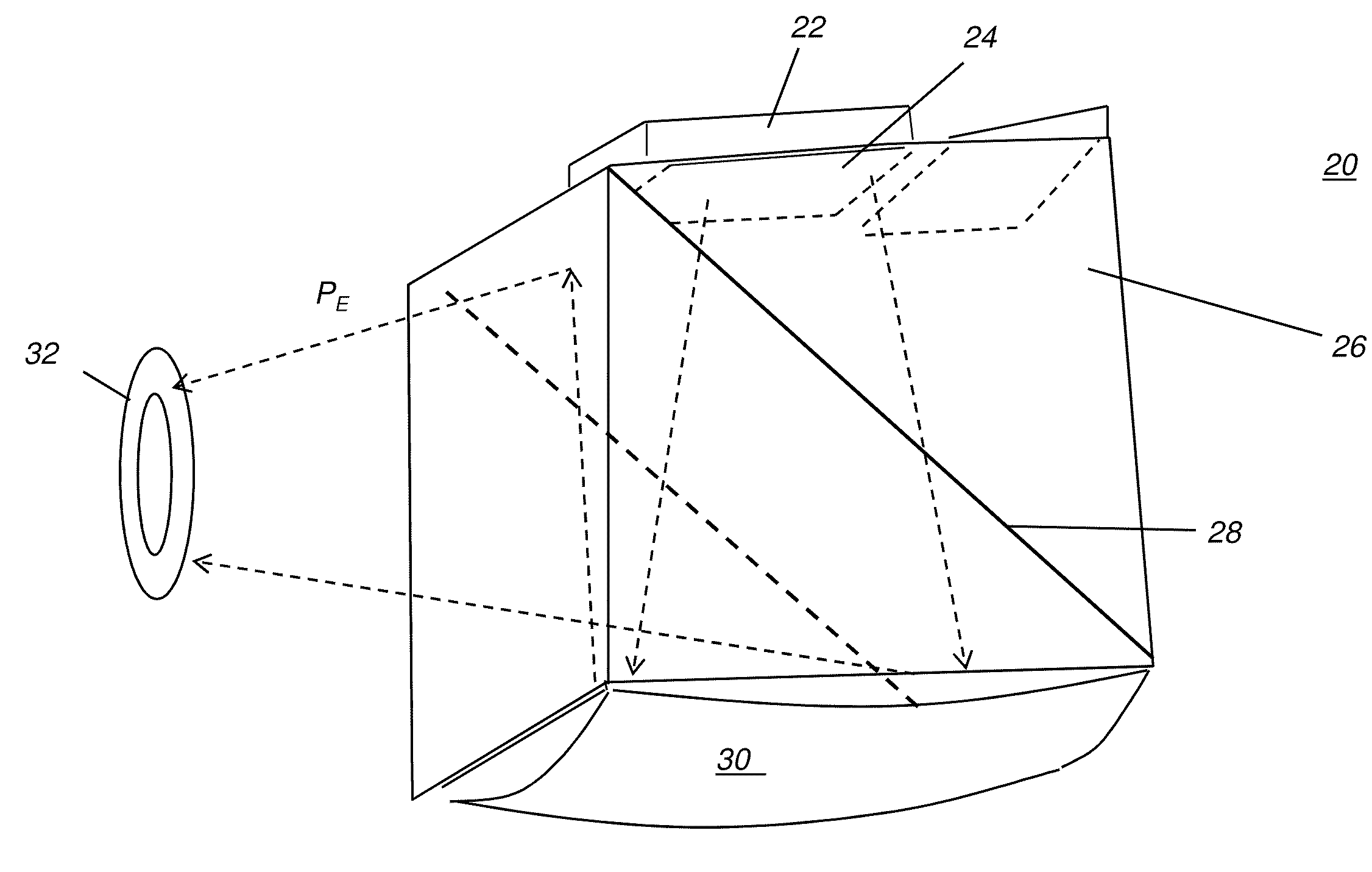
A see-through head-mounted optical apparatus for a viewer has at least one display module, each display module having a display energizable to form an image and a positive field lens optically coupled to the surface of the display and disposed to direct imaged light from the display toward a first surface of a prism. A curved reflector element is in the path of the imaged light through the prism and disposed at a second surface of the prism, opposite the first surface. The curved reflector element has a refractive surface and a curved reflective surface disposed to collimate imaged light received from the display and direct this light toward a beam splitter that is disposed within the prism and that is at an oblique angle to the collimated reflected light. The beam splitter redirects the incident collimated reflected light through the prism to form an entrance pupil for the viewer.

Description

CROSS REFERENCE TO RELATED APPLICATIONS[0001]Priority is claimed from U.S. Ser. No. 61 / 216,109, provisionally filed on May 13, 2009, entitled “An Optical Device Using an OLED Display Device”, in the names of David Kessler and Minoo Bablani, commonly assigned and incorporated herein by reference.STATEMENT REGARDING FEDERALLY SPONSORED RESEARCH OR DEVELOPMENT[0002]The present invention was developed with U.S. government support under contract No. W91C RB08C 0151 awarded by the U.S. Army. The government has certain rights in the invention.FIELD OF THE INVENTION[0003]This invention generally relates to head-mounted display systems for viewing electronically generated images that are superimposed upon the see-through field of view and more particularly relates to an apparatus and method for an arrangement of optical components to provide a head-mounted optical apparatus that provides a very wide field of view and large entrance pupils.BACKGROUND OF THE INVENTION[0004]Head-Mounted Display...

Claims


Application Information

Patent Timeline
IPC IPC(8): G02B27/01
CPCG02B5/30G02B6/06G02B2027/0123G02B2027/011G02B2027/0118G02B27/0172
Inventor KESSLER, DAVIDBABLANI, MINOO
Owner NVIS
Why Eureka
Try Eureka