Solid state lighting devices having remote luminescent material-containing element, and lighting methods

a technology of luminescent material and lighting device, which is applied in semiconductor devices, lighting and heating apparatus, light source combinations, etc., can solve the problems of incandescent light bulbs that incandescent light bulbs are relatively short life cycles, and incandescent light bulbs are very energy-inefficient light sources. , to achieve the effect of reducing the depth of the device, reducing the dimension of the device, and less spa

Active Publication Date: 2010-11-18
IDEAL IND LIGHTING LLC
View PDF15 Cites 92 Cited by
  • Summary
  • Abstract
  • Description
  • Claims
  • Application Information

AI Technical Summary

Problems solved by technology

It is well known that incandescent light bulbs are very energy-inefficient light sources—about ninety percent of the electricity they consume is released as heat rather than light.
Fluorescent light bulbs are more efficient than incandescent light bulbs (by a factor of about 10) but are still less efficient than solid state light emitters, such as light emitting diodes.
In addition, as compared to the normal lifetimes of solid state light emitters, e.g., light emitting diodes, incandescent light bulbs have relatively short lifetimes, i.e., typically about 750-1000 hours.
Fluorescent bulbs have longer lifetimes (e.g., 10,000-20,000 hours) than incandescent lights, but provide less favorable color reproduction.
Another issue faced by conventional light fixtures is the need to periodically replace the lighting devices (e.g., light bulbs, etc.).
Such issues are particularly pronounced where access is difficult (e.g., vaulted ceilings, bridges, high buildings, traffic tunnels) and / or where change-out costs are extremely high.
Light-producing device lifetime is typically much shorter, thus creating the need for periodic change-outs.
Although the development of light emitting diodes has in many ways revolutionized the lighting industry, some of the characteristics of light emitting diodes have presented challenges, some of which have not yet been fully met.
For example, solid state light emitters are commonly seen in indicator lamps and the like, and in some other types of lighting, but are not yet in widespread use for general illumination.
Back-scattered light that is scattered back into a light emitting diode has a very low probability of coming out of the chip, and hence, such-back-scattering results in a system loss of energy.
Self-absorption occurs when light that is absorbed, converted and re-emitted by luminescent material is re-absorbed by luminescent material or otherwise prevented from exiting the luminescent material-containing element, thus reducing performance (intensity) and efficiency.

Method used


Image

  • Solid state lighting devices having remote luminescent material-containing element, and lighting methods
  • Solid state lighting devices having remote luminescent material-containing element, and lighting methods
  • Solid state lighting devices having remote luminescent material-containing element, and lighting methods

Examples


fourth embodiment

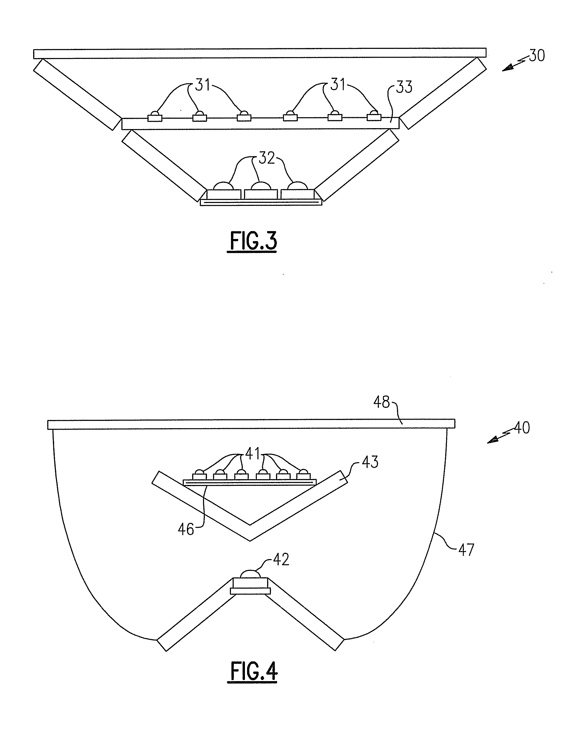
[0192]In the above description of the fourth embodiment, the luminescent material-containing element 43 is a reflector that has a phosphor. Alternatively, the luminescent material-containing element 43 can be a luminescent material (e.g., a phosphor) that can be a reflector or an element that can act as a luminescent material, or a reflector, or both.

[0193]The first group of solid state light emitters 41 can include light emitting diodes that emit red light, the second group of solid state light emitters 42 can include light emitting diodes that emit blue light and the luminescent material can be a phosphor that emits yellow light.

[0194]The lighting device 40 can utilize a single blue light emitting diode (alternatively, there could be plural blue light emitting diodes, if desired) that shines onto a phosphor-coated highly reflective diffuser white reflector as the luminescent material-containing element 43. The blue light emitting diode can be supported on a conic pedestal which al...

first embodiment

[0208]The expression “emission plane of a solid state light emitter,” (e.g., “an emission plane of the first solid state light emitter”), as used herein, means (1) a plane that is perpendicular to an axis of the light emission from the solid state light emitter (e.g., in a case where light emission is hemispherical, the plane would be along the flat part of the hemisphere; in a case where light emission is conical, the plane would be perpendicular to the axis of the cone), (2) a plane that is perpendicular to a direction of maximum intensity of light emission from the solid state light emitter (e.g., in a case where the maximum light emission is vertical, the plane would be horizontal), (3) a plane that is perpendicular to a mean direction of light emission (in other words, if the maximum intensity is in a first direction, but an intensity in a second direction ten degrees to one side of the first direction is larger than an intensity in a third direction ten degrees to an opposite ...

second embodiment

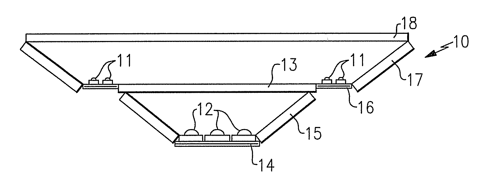
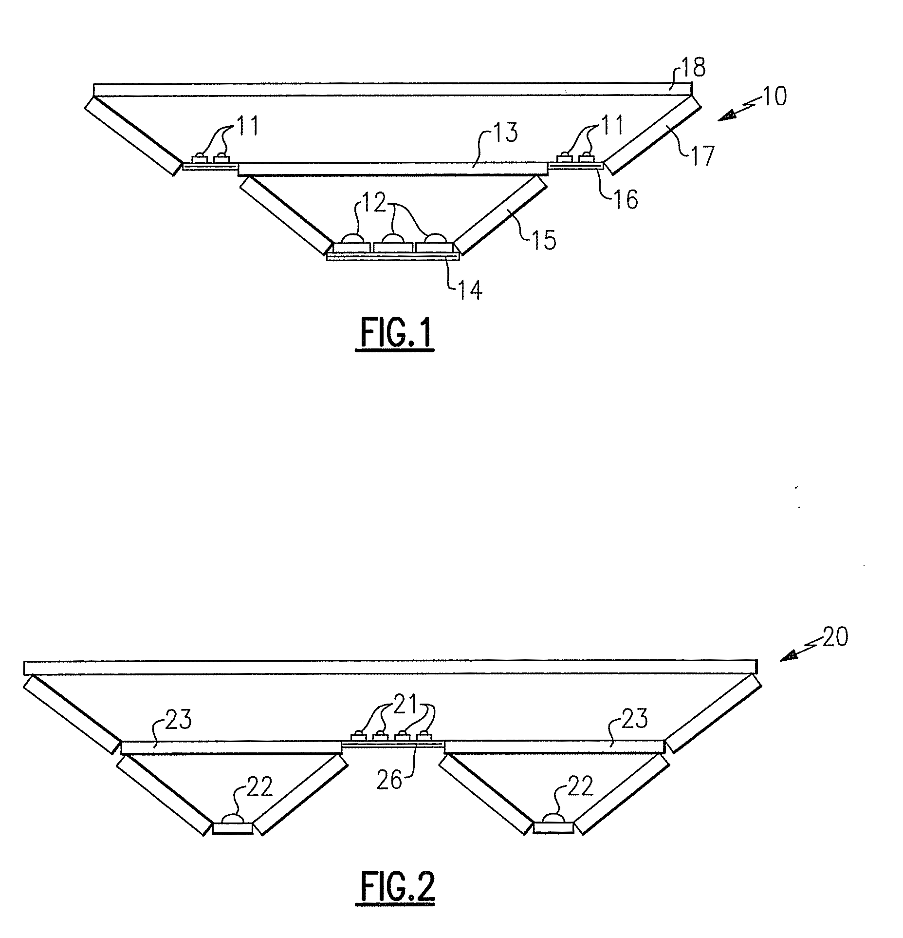
[0225]In some embodiments in accordance with the present inventive subject matter, the first solid state light emitter is mounted on a first support element, and the luminescent material-containing element defines a luminescent material-containing element opening in which the first support element is positioned. For example, in the second embodiment described above, each of the solid state light emitters in the first group of solid state light emitters 21 is mounted on a first support element (the substrate 26), and the annular luminescent material-containing element 23 defines a luminescent material-containing element opening in which the first support element 26 is positioned.

[0226]In some embodiments in accordance with the present inventive subject matter, the first solid state light emitter is mounted on the luminescent material-containing element. For example, in the first embodiment (and similarly in the second, third and sixth embodiments) described above, each of the solid s...


PUM

PropertyMeasurementUnit
CRIaaaaaaaaaa
transparentaaaaaaaaaa
dominant wavelengthaaaaaaaaaa

Abstract

A lighting device comprising a first group of solid state light emitters, an element containing luminescent material and a second group of solid state light emitters spaced from the element. In some embodiments, (1) at least 50% of light emitted by one of the first group does not mix with light emitted by the second group before the light emitted by the second group has entered the element, (2) at least 90% of exiting light emitted by the second group travels farther within the lighting device than 90% of exiting light emitted by the first group, (3) an average distance traveled by exiting light emitted by the second group is farther than an average distance traveled by exiting light emitted by the second group, and/or (4) light emitted by the first group directly exiting the lighting device exits the lighting device without being incident upon the element.

Description

FIELD OF THE INVENTIVE SUBJECT MATTER [0001]The present inventive subject matter relates to solid state lighting devices having solid state light emitters that are spaced from luminescent material-containing elements and that are spaced from other solid state light emitters. In some embodiments, the present inventive subject matter relates to lighting devices in which light emitted by one group of solid state light emitters travels farther within the lighting device than light emitted by another group of solid state light emitters.BACKGROUND [0002]There is an ongoing effort to develop systems that are more energy-efficient. A large proportion (some estimates are as high as twenty-five percent) of the electricity generated in the United States each year goes to lighting, a large portion of which is general illumination (e.g., downlights, flood lights, spotlights and other general residential or commercial illumination products). Accordingly, there is an ongoing need to provide lighti...

Claims


Application Information

Patent Timeline
Patent Type & Authority Applications(United States)
IPC IPC(8): F21V9/16F21Y113/20
CPCB60Q1/0052B60Q1/0058F21Y2113/02F21V9/16F21Y2101/02F21K9/00F21Y2113/20F21Y2115/10F21K9/68F21V7/26F21V7/30F21V9/30F21Y2103/20
Inventor PICKARD, PAUL KENNETH
Owner IDEAL IND LIGHTING LLC
Why Eureka
Try Eureka