Light-emitting module and display device having the same

a technology of light-emitting modules and display devices, which is applied in the direction of lighting and heating apparatus, planar/plate-like light guides, instruments, etc., can solve the problems of low light-emitting efficiency of leds, corresponding increase of manufacturing costs of backlight assemblies, and reduced light-emitting efficiency. , the effect of improving the uniformity of luminance and heat-radiating efficiency

Active Publication Date: 2010-11-18
SAMSUNG DISPLAY CO LTD
View PDF48 Cites 52 Cited by
  • Summary
  • Abstract
  • Description
  • Claims
  • Application Information

AI Technical Summary

Benefits of technology

[0009]One or more embodiments of the present invention provide a light-emitting module capable of obtaining emitted light in which heat-radiating efficiency may be enhanced using a small number point light source.
[0016]According to one or more embodiments of the present invention, in a light-emitting module and a display device having the light-emitting module, light-emitting efficiency may be enhanced and the arrangement of point light sources may be optimized, so that a required amount of emitted light may be obtained using a small number of the point light sources. Uniformity of luminance and heat-radiating efficiency may also be enhanced.

Problems solved by technology

However, only about 20% to about 30% of the applied current is used by the LED for emitting light, and the remaining current is consumed to generate heat energy.
Since the heat energy is generated during light emitting operation, the light-emitting efficiency of the LED may be low.
However, as the number of the LEDs is increased, manufacturing costs of the backlight assembly is correspondingly increased.

Method used


Image

  • Light-emitting module and display device having the same
  • Light-emitting module and display device having the same
  • Light-emitting module and display device having the same

Examples


Embodiment Construction

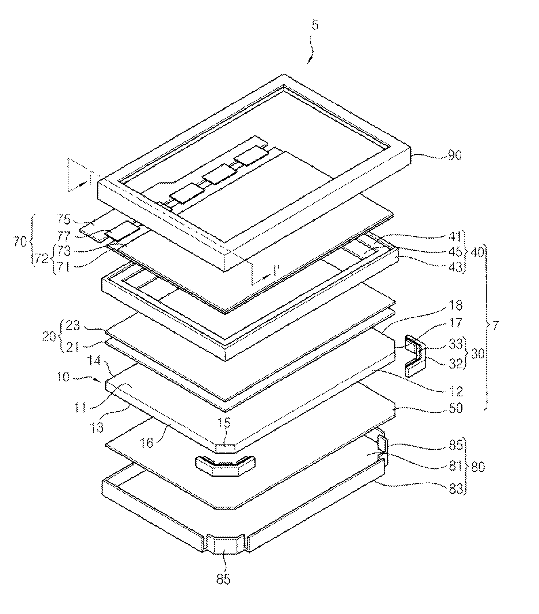
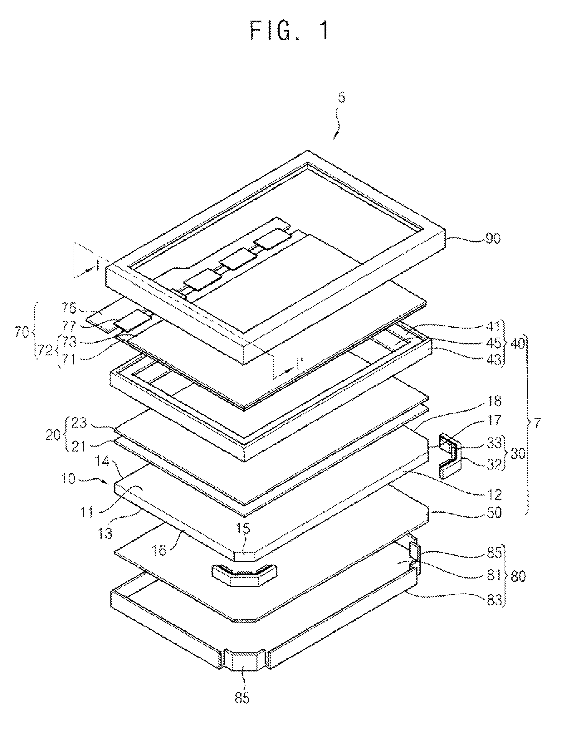
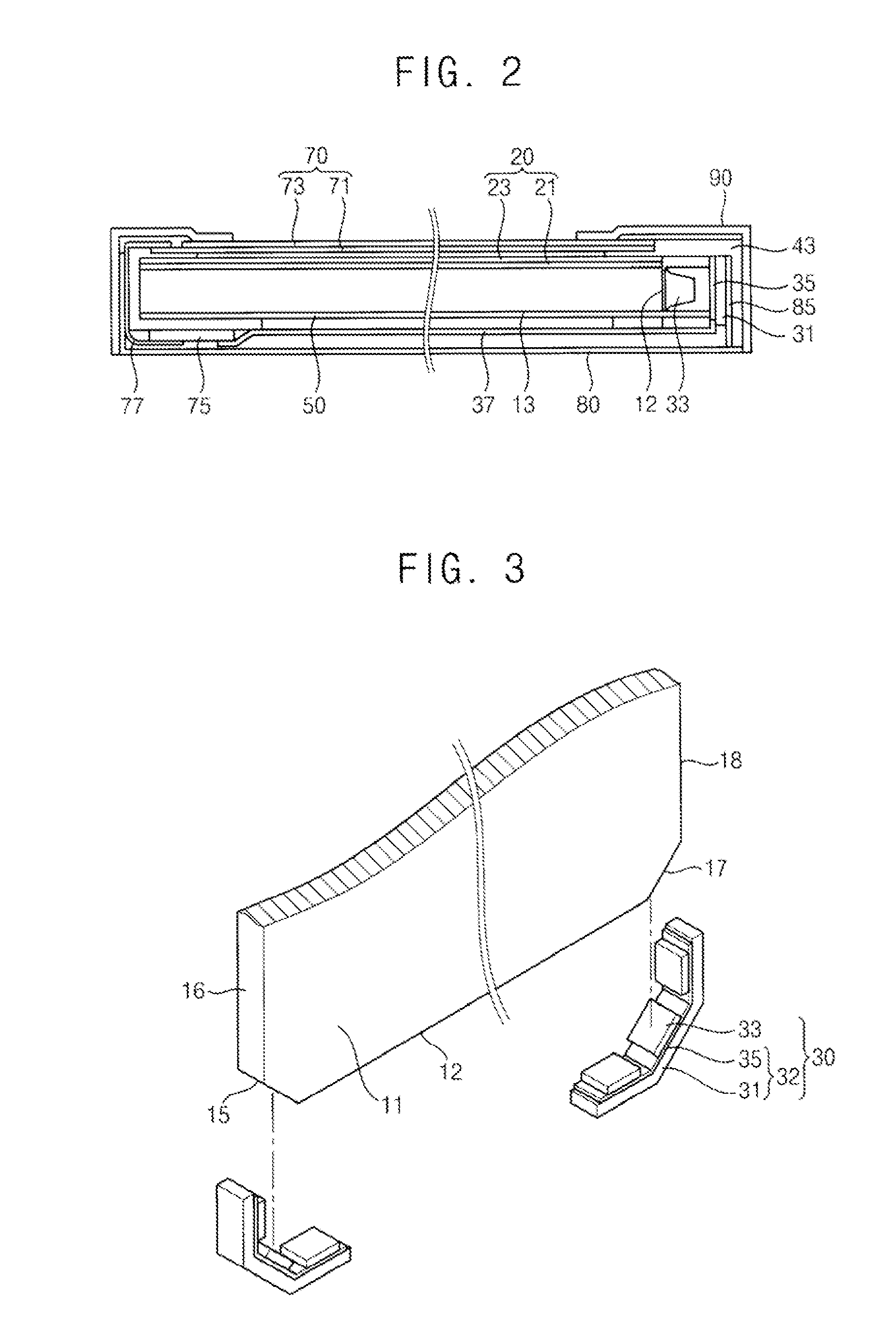
[0031]Embodiments of the present invention are described more fully hereinafter with reference to the accompanying drawings, in which one or more embodiments of the present invention are shown. The present invention may, however, be embodied in many different forms and should not be construed as being limited to the embodiments set forth herein. Rather, the scope of the present invention will only be defined by the appended claims. In the drawings, the sizes and relative sizes of layers and regions may be exaggerated for clarity.

[0032]It will be understood that when an element or layer is referred to as being “on,”“connected to” or “coupled to” another element or layer, it may be directly on, connected to or coupled to the other element or layer, or intervening elements or layers may be present. In contrast, when an element is referred to as being “directly on,”“directly connected to” or “directly coupled to” another element or layer, there are no intervening elements or layers pres...


PUM


Abstract

A light-emitting module includes a light guide plate and a light source unit in accordance with an embodiment. The light guide plate include an upper surface, a lower surface facing the upper surface, a plurality of side surfaces connecting the upper surface and the lower surface, and a cross-sectional surface connected to at least one of the side surfaces. The light source unit includes a substrate disposed in correspondence with the cross-sectional surface and a point light source mounted on the substrate to emit light to the cross-sectional surface. Thus, light-emitting efficiency may be enhanced and the arrangement of point light sources may be optimized, so that a required amount of emitted light may be obtained using a small number of the point light sources. In addition, uniformity of luminance and heat-radiating efficiency may also be enhanced.

Description

PRIORITY STATEMENT[0001]This application claims priority under 35 U.S.C. §119 to Korean Patent Application No. 2009-0041482, filed on May 13, 2009 in the Korean Intellectual Property Office (KIPO), the contents of which are herein incorporated by reference in their entirety.BACKGROUND[0002]1. Technical Field[0003]One or more embodiments of the present invention relate to a light-emitting module and a display device having the light-emitting module. More particularly, one or more embodiments of the present invention relate to a light-emitting module which guides emitted light using a light guide plate to form surface light, and a display device having the light-emitting module.[0004]2. Description of the Related Art[0005]Generally, flat panel display devices, such as the liquid crystal display (LCD) devices, have various advantages, such as having thinner thickness, lighter weight, lower driving voltage and lower power consumption, etc., compared to other types of display devices. Th...

Claims


Application Information

Patent Timeline
Patent Type & Authority Applications(United States)
IPC IPC(8): F21V8/00F21V7/04F21V5/04
CPCG02B6/002G02B6/0091G02B6/0083G02B6/0021
Inventor KIM, HYOUNG-JOOYOON, JU-YOUNGKWON, JAE-JOONGCHO, CHI-OPARK, JIN-HEEKIM, JOO-YOUNGSHIM, SUNG-KYU
Owner SAMSUNG DISPLAY CO LTD
Why Eureka
Try Eureka