Monitoring of network connections

a network connection and monitoring technology, applied in the field of data communication, can solve problems such as complete connection loss, and achieve the effects of reducing the snr margin, increasing the headline bit rate, and improving latency

Active Publication Date: 2010-11-18
BRITISH TELECOMM PLC
View PDF4 Cites 25 Cited by
  • Summary
  • Abstract
  • Description
  • Claims
  • Application Information

AI Technical Summary

Benefits of technology

[0019]It will thus be appreciated, that the lower the SNR Margin, the higher the headline bit rate that will be achievable (i.e. assuming that there are no errors). Whilst, the higher the SNR Margin, the more likely that the connection will operate in a stable manner, even in a fluctuating noise environment.
[0020]Fast/interleave mode switches the depth of interleave between no interleave (FAST mode) and any of the depths of interleave defined in the currently applicable ADSL standards (e.g. the ITU G.992.x standards). In many implementations, only the lowest level of interleave (a depth of 2, where units in a single code word which are adjacent before interleaving are separated by one interleaved unit from another word after interleaving) is used at the moment; however, this may change in the future. As is well known in the art, use of interleave protect...

Problems solved by technology

An automatic or forced re-synchronisation is one which occurs ...

Method used


Image

  • Monitoring of network connections
  • Monitoring of network connections
  • Monitoring of network connections

Examples


main embodiment

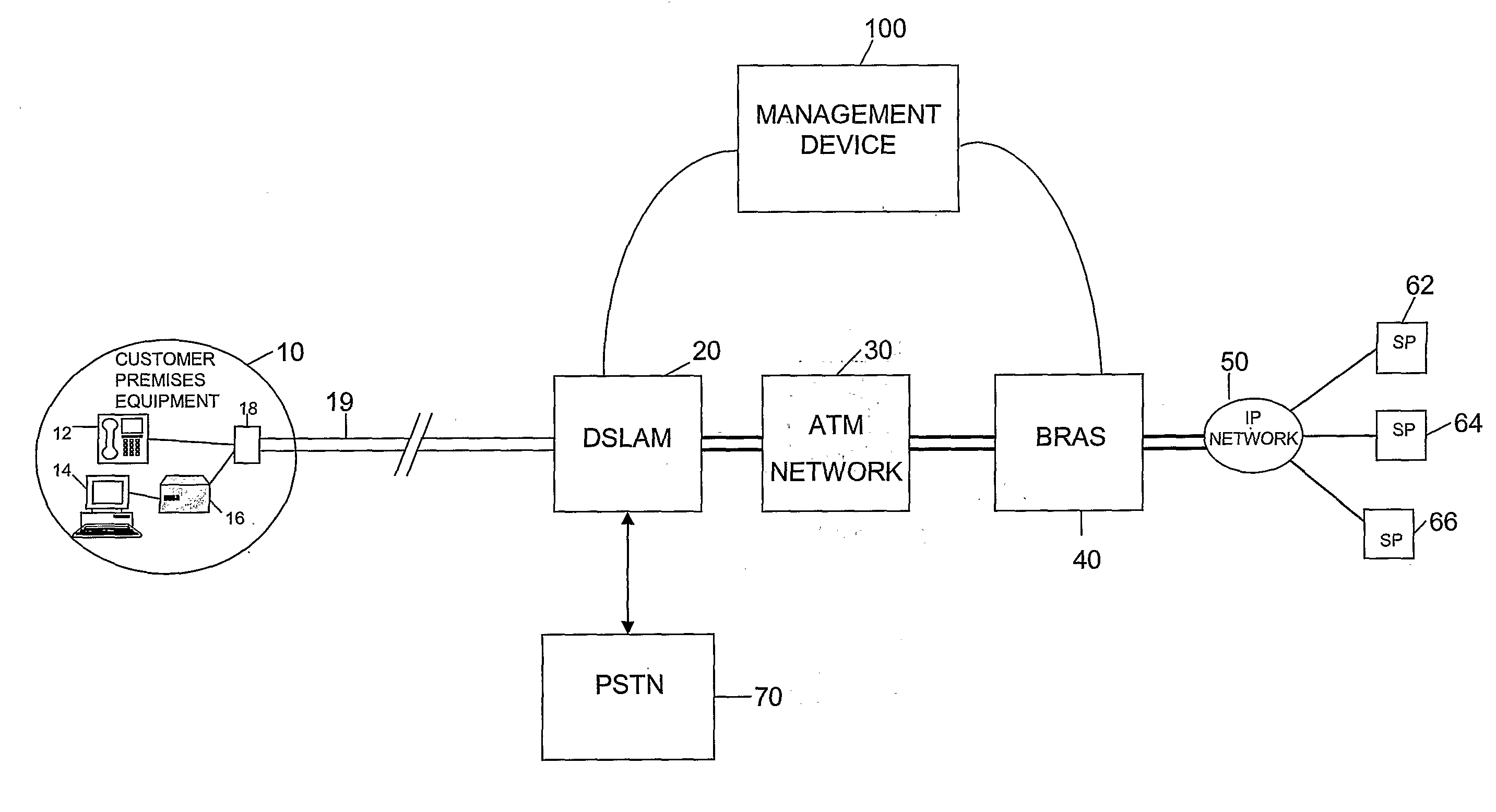
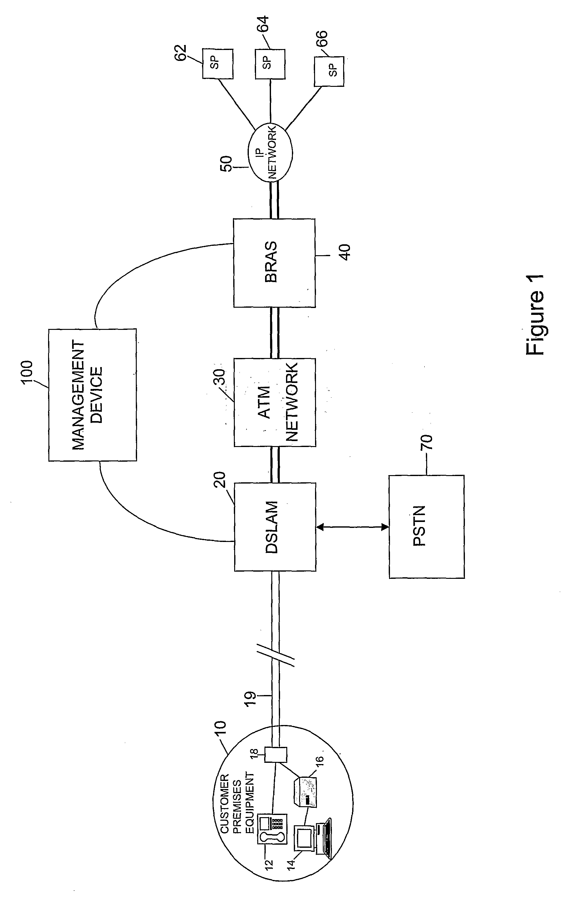
[0037]Referring to FIG. 1, a first embodiment of the present invention is illustrated in overview. A copper pair loop 19 (which forms part of the access network which extends between customer premises equipment 10 and the BRAS 40) connects customer premises equipment 10 to a DSLAM 20 located within a local exchange (also known as a central office in the US). The DSLAM separates normal voice traffic and data traffic and sends the voice traffic to the Public Switched Telephone Network (PSTN) 70. The data traffic is passed on through an Asynchronous Transfer Mode (ATM) network 30 which forms the remainder of the access network 19, 20, 30 (in the present embodiment, the ATM network 30 is British Telecom (BT)'s Multi Service intranet Platform (MSiP) ATM network). Connected to the ATM network 30 is a Broadband Remote Access Server (BRAS) 40 at which several IP traffic flows or ATM circuits from (and to) multiple Service Providers (SP's) 62, 64, 66 are aggregated (and disaggregated) via an...


PUM


Abstract

A management device (100) for use in an access network (10, 19, 20, 30, 40, 100) including a plurality of data connections (18, 19, 20) between end user devices (10) and an aggregation transceiver device (20) where the connections (18, 19, 20) are aggregated for onward connection through the access network (20, 30, 40), the access network storing in association with each data connection a Dynamic Line Management, DLM, profile which specifies a set of values for a plurality of parameters associated with the respective data connection, together with a stability level specifying a desired level of stability for the data connection. The device comprises means for receiving monitoring data specifying the stability of each respective data connection over a predetermined period of time; means for selecting a DLM profile to be applied to the connection in dependence on both the monitoring data and the stored stability level associated with the data connection; and means for requesting an OSS system of the access network to apply the selected profile to the data connection.

Description

FIELD OF THE INVENTION[0001]The present invention relates to data communication. In particular, it relates to the management of an access network including Digital Subscriber Line (DSL) connections.BACKGROUND TO THE INVENTION[0002]Dynamic Line Management (DLM) is a technique for improving the stability of DSL connections. It is particularly useful when operating DSL connections at close to their maximum speed, because under these conditions external noise affecting the transmitted signal can cause the transceivers to be unable to successfully recover the signal to be transmitted with sufficient reliability to enable the connection to be maintained. If this occurs, the connection needs to be re-established. This is referred to as a re-synch or a re-train and the user notices a temporary loss of service while the connection is re-established. Re-synchs are generally found to be particularly annoying by end users.[0003]DLM seeks to minimise such re-synchs by automatically analysing DSL...

Claims


Application Information

Patent Timeline
IPC IPC(8): H04L12/26
CPCH04L12/2602H04L43/00H04L43/0811H04L43/0829H04M3/304H04L43/16H04M11/062H04M3/2227H04L43/0852
Inventor CROOT, CHRISTOPHER MARCUSLINNEY, TREVOR PHILIPCOOK, JOHN WOLSEY
Owner BRITISH TELECOMM PLC
Why Eureka
Try Eureka