High definition impedance imaging

a technology of impedance imaging and high definition, applied in the field of high definition impedance imaging, can solve problems such as computational inefficiency of methods, and achieve the effect of reducing the number of iterations

Inactive Publication Date: 2010-11-18
WEXLER ALVIN +3
View PDF11 Cites 16 Cited by
  • Summary
  • Abstract
  • Description
  • Claims
  • Application Information

AI Technical Summary

Benefits of technology

[0014]The present invention seeks to provide a method to be used in conjunction with the Fry et al. methodology in order to produce a computationally efficient system that reduces the number of iterations required to generate a conductivity

Problems solved by technology

The inverse problem associated with a single excitation configuration, that is the problem of reconstructing from the measured data an image representing the nonuniform distribution of conductivity ove

Method used


Image

  • High definition impedance imaging
  • High definition impedance imaging
  • High definition impedance imaging

Examples


Embodiment Construction

[0048]The invention will be described for the purposes of illustration only in connection with certain embodiments; however, it is to be understood that other objects and advantages of the present invention will be made apparent by the following description of the drawings according to the present invention. While a preferred embodiment is disclosed, this is not intended to be limiting. Rather, the general principles set forth herein are considered to be merely illustrative of the scope of the present invention and it is to be further understood that numerous changes may be made without straying from the scope of the present invention.

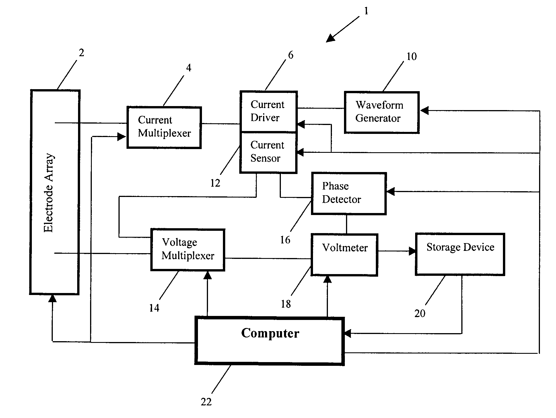
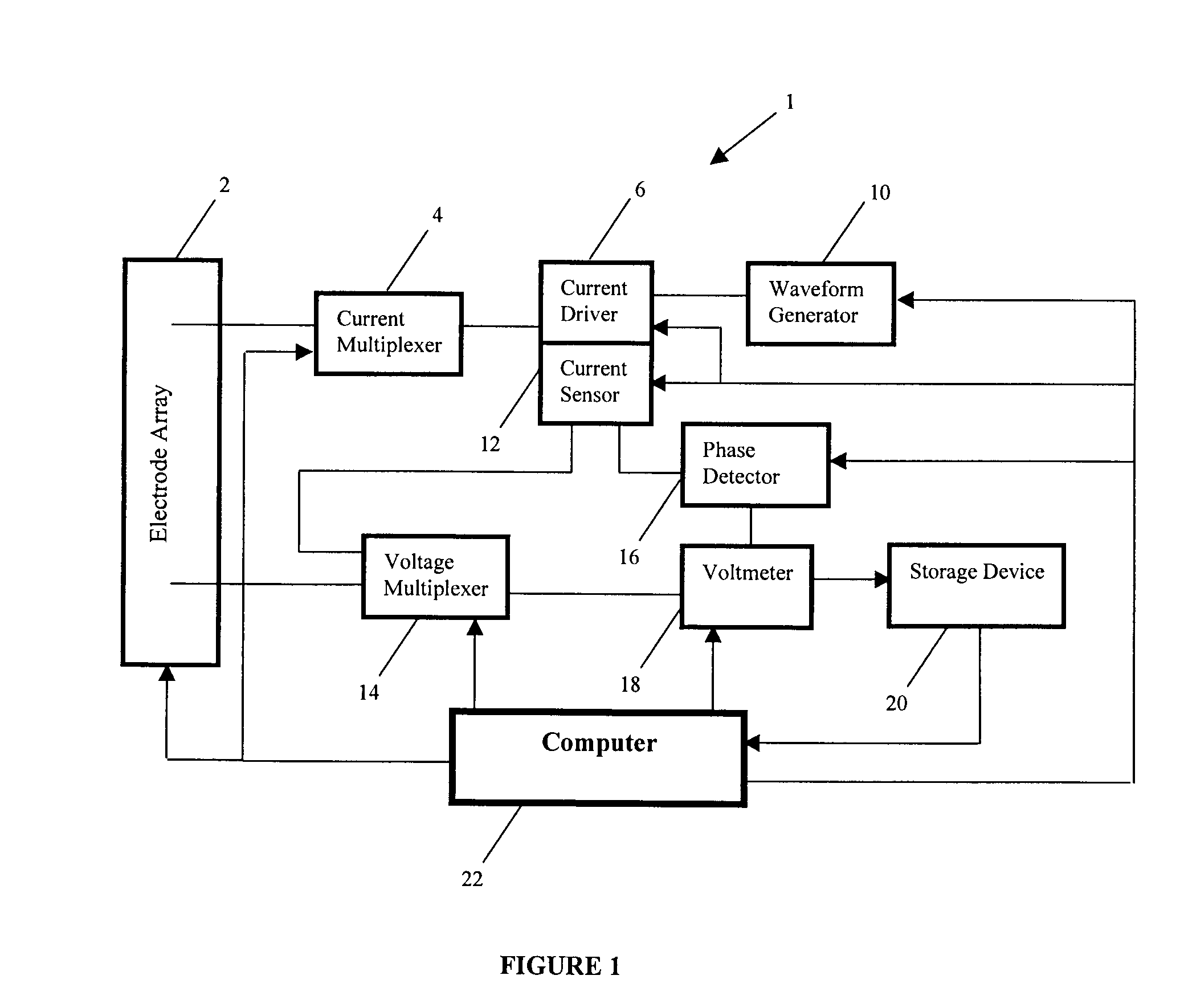
[0049]In FIG. 1, there is shown a block diagram of a system 1 according to an embodiment of the present invention. The system 1 comprises an electrode array 2 for placement on or around the medium such as a human body or a subterranean region of the earth's surface within which an object to be imaged is located. The electrode array 2 includes a plurali...


PUM


Abstract

A method for producing a computationally efficient system that reduces the number of iterations required to generate a conductivity image pattern of a subsurface object, and its attendant conductivity distribution, through a solution to the system of field equations that simultaneously satisfies all of the boundary conditions and conserves internal current flux densities.

Description

FIELD OF THE INVENTION [0001]The present invention relates to an improved method and system for detecting and imaging discrete subsurface objects or spatially-continuous inhomogeneous regions within a body which have contrasting conductivity or, more generally, admittivity (i.e. the inverse of specific impedance) within the body. The invention may be used for imaging using electrical currents, sound signals, or other excitations.BACKGROUND TO THE INVENTION [0002]In a number of disparate technical fields, there has been a constant effort to find improved methods of detecting subsurface objects such as tumours in the human body or land mines underneath the Earth's surface. These methods, known as electrical impedance tomography (EIT), are based upon imaging electrical conductivity or admittivity distributions within a body and generating an image of the subsurface objects based on these electrical conductivity or admittivity values. (The terms “conductivity” and “admittivity” are used...

Claims


Application Information

Patent Timeline
IPC IPC(8): G06K9/36G06K9/00
CPCA61B5/0536G01V3/02G01N27/041A61B5/416
Inventor WEXLER, ALVINO'CONNOR, PATRICK ADRIANMURUGAN, RAJEN MANICONZHENG, ZHONGO'CONNOR, MISTY
Owner WEXLER ALVIN
Why Eureka
Try Eureka