In-mould label and method for manufacturing thereof

a mould label and label technology, applied in the field of mould labels, can solve the problems of more severe wear and tear of the object, and achieve the effects of reducing the risk of tearing, facilitating the adaptation of the label to the mould wall, and being highly resistant to tearing

Inactive Publication Date: 2010-11-18
I S D I
View PDF1 Cites 32 Cited by
  • Summary
  • Abstract
  • Description
  • Claims
  • Application Information

AI Technical Summary

Benefits of technology

[0015]One advantage of the present invention is that an apparatus as illustrated in FIG. 6 for the manufacturing of standard in mould labels as depicted in FIG. 1(a) can be adapted very easily and at minor costs to become suitable for the manufacturing of the claimed in mould labels.
[0016]The in mould labels manufactured as explained above can then be cut to the desired dimensions and positioned into a mould for injection moulding or blowmoulding, the second, transparent film being in contact with the mould wall. Adhesion of the label to the mould walls can be enhanced by vacuum suction or, preferably, by electrostatically charging the label prior to its positioning into the mould. The polymer melt or the reactive resin of the article to be manufactured is then injected into the mould and contacts the backing surface of the label, which is thus incorporated into the manufactured polymeric article. Similarly a polymeric parison is blown in a blowmoulding mould until it contacts the mould walls and thus incorporates the in mould label. The article thus produced is extracted and is ready for shipment.
[0017]An article produced with the process of the present invention is advantageous in that it comprises a label highly resistant to tearing, since it is incorporated into the bulk of the article, and to wear as the printed pattern is protected by the top transparent film.
[0018]Further details and advantages of the present invention are explained in the next section. The Figures are only meant to illustrate the invention and are not intended to limit the scope of the claims.
[0019]FIG. 1(a) to (d) shows various embodiments of in mould labels known in the art applied to a polymeric article.
[0020]FIG. 2(a)&(b) shows an embodiment of an in mould label of the present invention and the same applied to a polymeric article.

Problems solved by technology

If a varnish is sufficient to protect the printed pattern under “normal” or light conditions of use, it is unsatisfactory when the article is exposed to more severe conditions of wear such as encountered by vessels repeatedly washed in a dishwasher, car parts hit by chips projections, luggage (mis-)handled in airports, surfaces exposed to UV light, boat parts in contact with salt water, equipment exposed to sand projections, etc.
Though solving the problem of wear resistance of the printed pattern, this solution has some drawbacks.

Method used


Image

  • In-mould label and method for manufacturing thereof
  • In-mould label and method for manufacturing thereof
  • In-mould label and method for manufacturing thereof

Examples


examples

[0050](a) IML Manufacturing

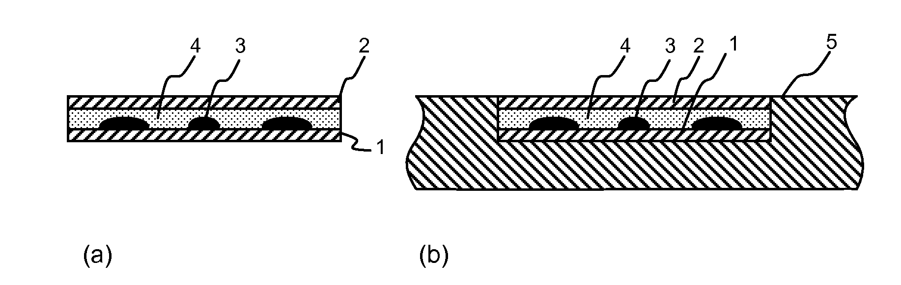
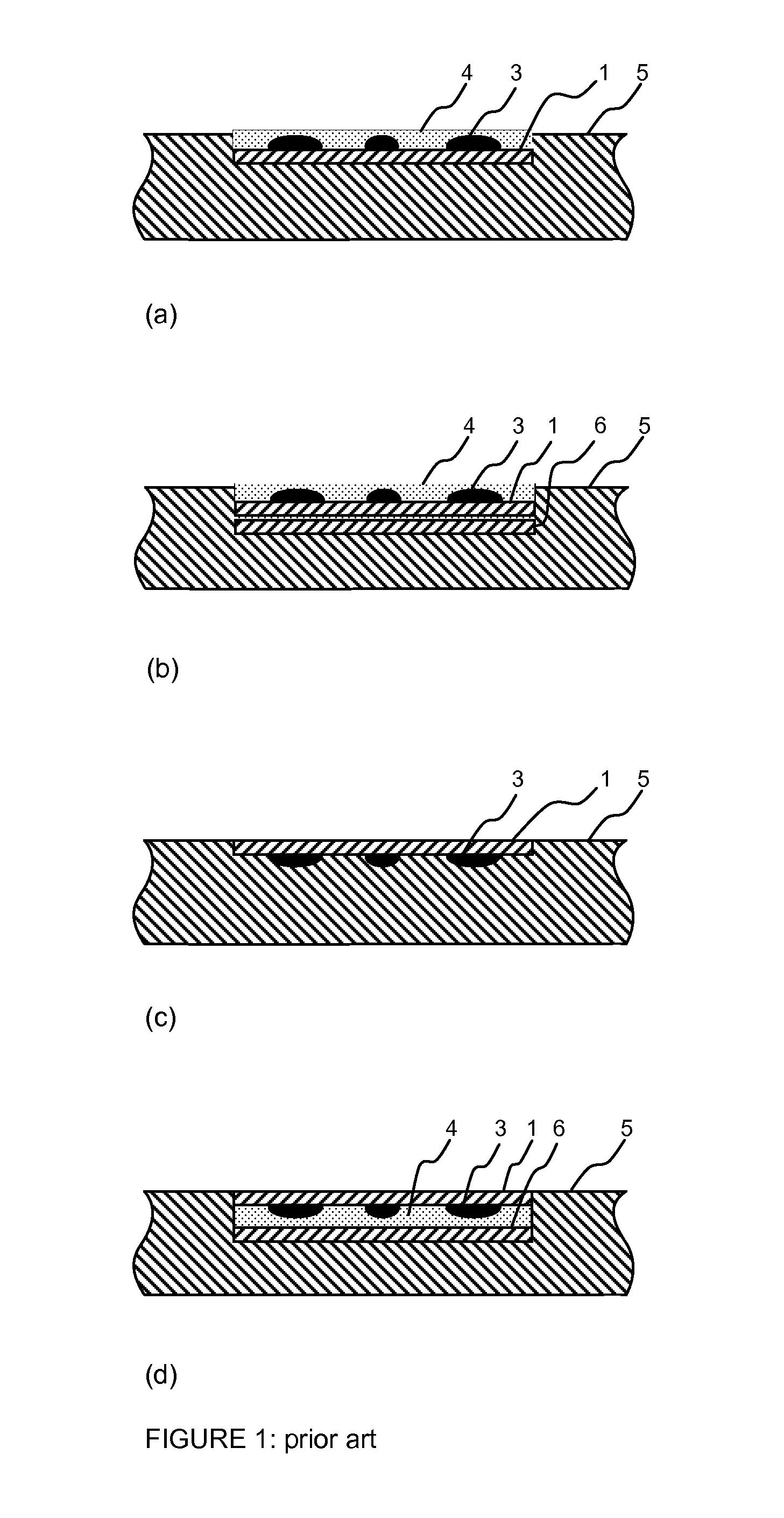
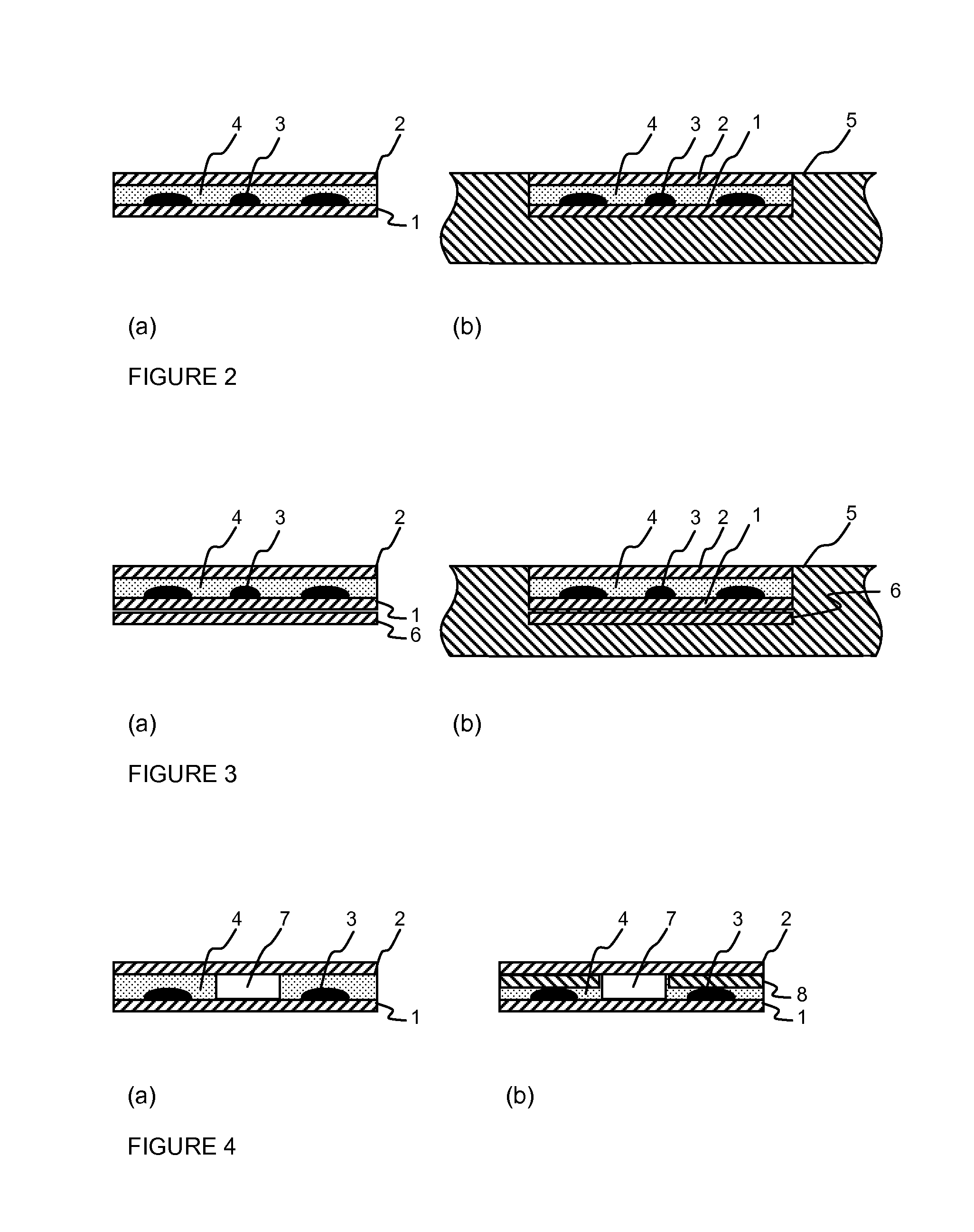
[0051]An IML according to the present invention was manufactured as follows. A decorative pattern was printed positively on a non pre-treated 50 μm PP solid film (1) well suited for traditional IML applications with traditional offset UV inks (UV rays drying). The printed pattern covered 100% of the label with a high density of ink.

[0052]A solvent based adhesive was applied on a second, 20 μm PP transparent solid film (2); the coated transparent film (2) was then dried through a 5 meters long drying tunnel and subsequently laminated onto the printed surface (1a) of the printed film (1). The thus obtained IML's were left 24 h to complete the curing / drying process.

[0053](b) Moulding of the IML

[0054]A number of labels were die-cut from the reel (22) and were transferred onto an inner wall of an injection mould designed for a food long life transparent PP-container. After injecting the part, the IML showed a perfect adhesion to the moulded part. No undesired e...


PUM

PropertyMeasurementUnit
thicknessaaaaaaaaaa
thicknessaaaaaaaaaa
thicknessaaaaaaaaaa

Abstract

The present invention concerns an in mould label comprising a polymeric or cellulosic carrier base film (1) having a first decorative surface (1a) and a second, backing surface (1b), said label comprising a pattern (3) printed on said first decorative surface (1a) thereof, said printed first surface (1a) being laminated with a transparent protective top film (2), affixed thereto by means of an adhesive (4), the printed pattern (3) being visible through said transparent protective top film (2). It also concerns a method for manufacturing such a label and a method for incorporating it onto the surface of a polymeric article.

Description

TECHNICAL FIELD[0001]The present invention relates to in mould labels (IML) which are particularly wear resistant and economical. It also concerns a method for manufacturing said labels and a method for producing polymeric articles comprising said in mould label.BACKGROUND OF THE INVENTION[0002]In mould labels, commonly referred to as IML are well known in the art and comprise a carrier base, generally consisting of a polymeric or cellulosic carrier film, on which a decorative pattern or a written message is printed; a protective varnish is then applied as a top layer to protect the decorative pattern (cf. FIG. 1(a)). The thus obtained label is then positioned against a wall of a mould for injection moulding or for blow moulding, held in place by means known in the art, such as electrostatic forces or vacuum suction, and a polymeric article is moulded by injecting a mass of polymeric melt or by blowing a polymeric parison against the mould walls on which the IML is applied. Examples...

Claims


Application Information

Patent Timeline
Patent Type & Authority Applications(United States)
IPC IPC(8): B32B3/10B32B38/14B29C45/16B29C49/00B29C51/12B32B1/00
CPCB29C45/14811Y10T428/1334B29K2715/006B29K2995/002B29K2995/0087B32B27/10G09F3/04B32B7/045B32B7/12B32B23/08B32B27/08B32B27/16B32B27/18B32B27/20B32B27/302B32B27/304B32B27/32B32B27/34B32B27/36B32B27/38B32B27/40B32B3/08B32B2255/10B32B2255/12B32B2255/26B32B2270/00B32B2307/412B32B2307/554B32B2307/71B32B2307/7242B32B2307/75B32B2439/00B32B2439/60B32B2439/70B32B2519/00B32B2605/00Y10T428/13Y10T428/24851Y10T428/1352B29C2045/14918B32B7/05
Inventor DI DUCA, ERIC
Owner I S D I
Why Eureka
Try Eureka