Ventilating device for providing a zone of clean air.

a technology of clean air and ventilation device, which is applied in the direction of ventilation details, space heating and ventilation details, domestic heating details, etc., can solve the problems of high noise level, high air velocity, and disturbing effects, and achieves the effect of reducing noise, reducing noise, and reducing nois

Active Publication Date: 2010-11-18
AVIDICARE
View PDF23 Cites 5 Cited by
  • Summary
  • Abstract
  • Description
  • Claims
  • Application Information

AI Technical Summary

Benefits of technology

[0002]The object of a ventilating device as above is to create a uniform and stable downward air flow which prevents bacteria-bearing and other pollutant particles from entering the workplace region from the surrounding environment and carries away pollutants generated within the clean air zone.
[0003]The state of the art is based on blowing vertically downwards to provide the workplace region, e.g. an operating region, with an air flow velocity of 0.1-0.6 m / s. Achieving this entails a high initial air velocity of at least double, resulting in disturbing effects, e.g. turbulence, arising from, for example, operating lighting or other equipment situated between the ventilating device and the workplace region. The high air velocity also creates strong secondary air flows outside the workplace region which keep bacteria-bearing and other particles suspended, increasing the risk of contamination of the workplace region. High air velocity also subjects personnel to draughts and high noise levels.
[0007]Said air stop and guide units also help to minimize the increased downward velocity which occurs when the air flows from mutually adjacent air supply units meet in an uncontrolled manner. This is because the air stop and guide units according to the invention are so configured that they guide parts of the air flows from adjoining air supply units outwards from the centre of the clean air zone instead of towards the air supply units, and other parts of the air flows from adjoining air supply units in towards the centre of the clean air zone instead of towards the air supply units. This means that the points where the air flows from two adjoining air supply units meet are almost free from turbulence and that the air flows are instead caused to cooperate in a uniform and turbulence-free downward air flow.

Problems solved by technology

Achieving this entails a high initial air velocity of at least double, resulting in disturbing effects, e.g. turbulence, arising from, for example, operating lighting or other equipment situated between the ventilating device and the workplace region.
The high air velocity also creates strong secondary air flows outside the workplace region which keep bacteria-bearing and other particles suspended, increasing the risk of contamination of the workplace region.
High air velocity also subjects personnel to draughts and high noise levels.
The disadvantage of air supply units in a closed pattern, e.g. in a circle, is that a slight negative pressure is created in the centre of the circle and exerts a suction force which draws bacteria-bearing and other pollutant particles in between the respective air supply units and into the clean air zone in the lower portion of the workplace region.

Method used


Image

  • Ventilating device for providing a zone of clean air.
  • Ventilating device for providing a zone of clean air.
  • Ventilating device for providing a zone of clean air.

Examples


Embodiment Construction

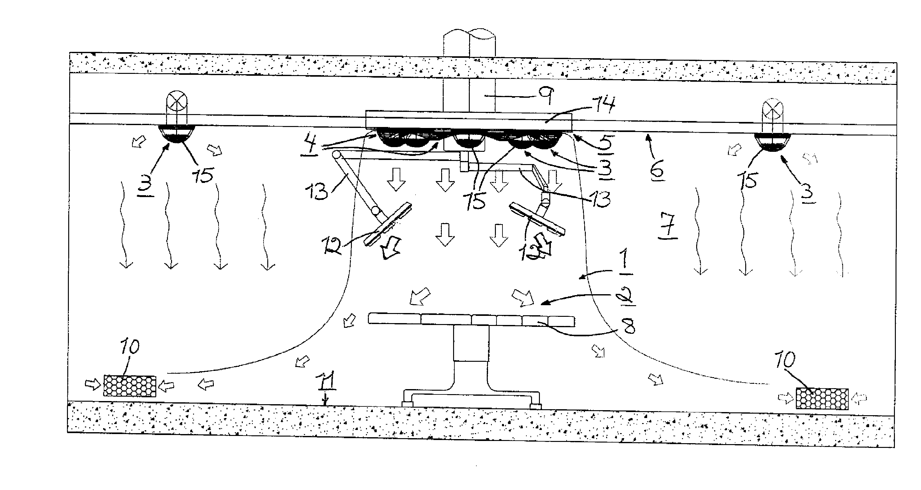
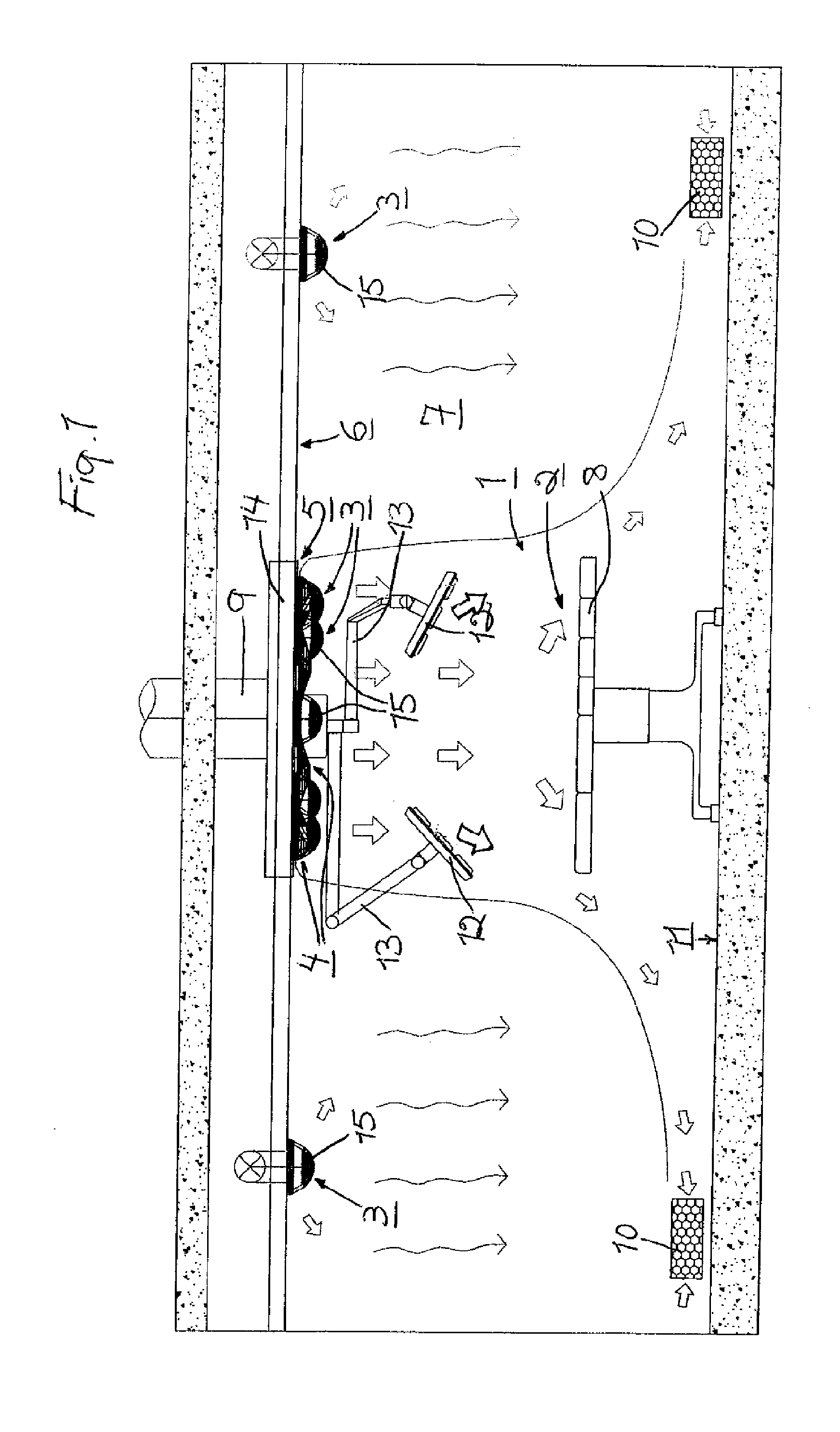
[0014]The ventilating device according to FIG. 1 is intended to create a zone 1 of clean air between the ventilating device and a workplace region, here an operating region 2 in the healthcare sector. The ventilating device comprises air supply units 3 which may be of a conventional type and are adapted to generating laminar air flows intended to constitute said clean air zone 1.

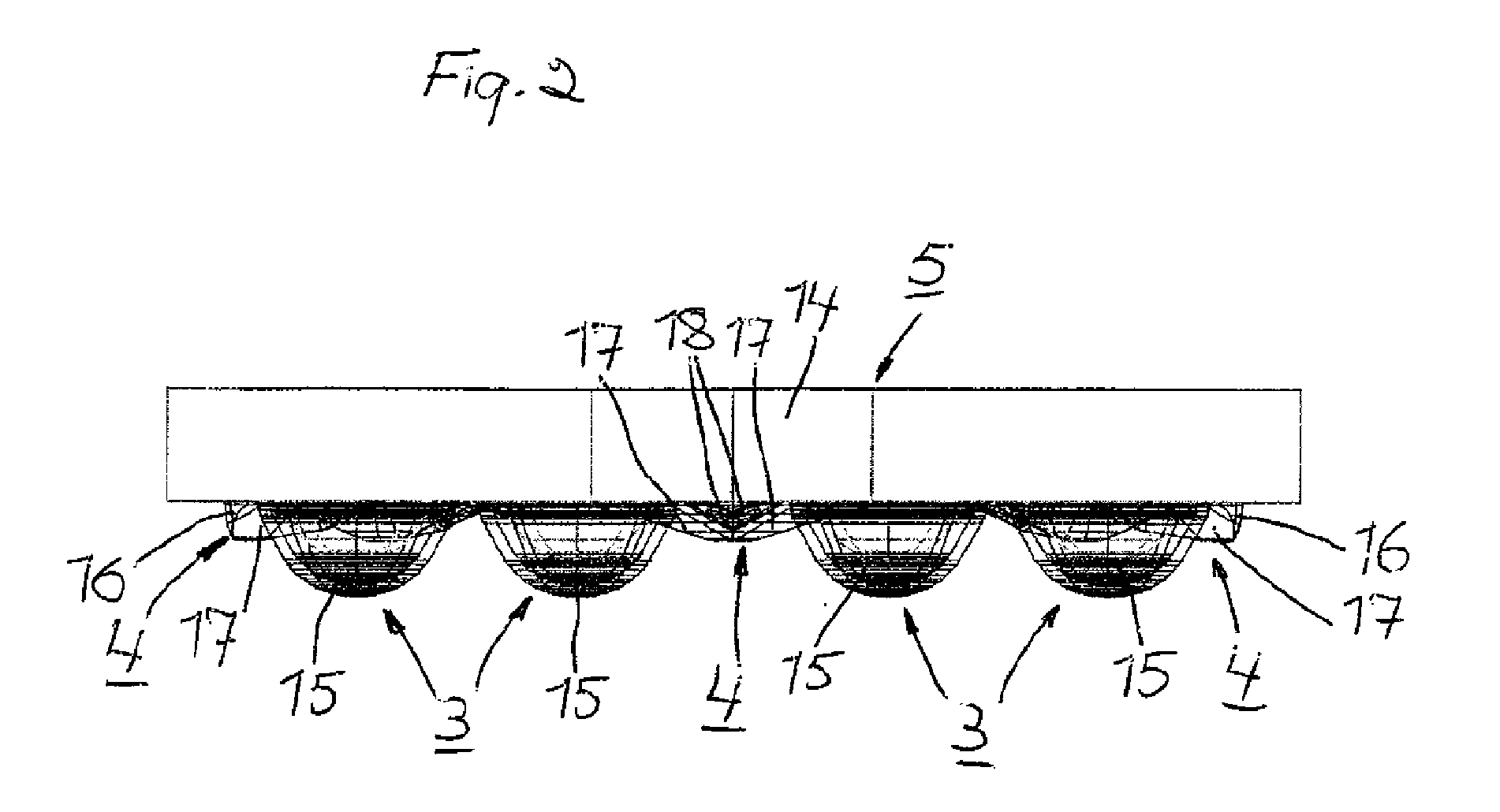
[0015]With the object of achieving, as compared with each individual air supply unit 3, a total air flow with a significantly greater spread which therefore serves a significantly larger region within which personnel have more freedom of movement for their work, the ventilating device according to the invention comprises at least three air supply units 3 disposed in a closed trilateral pattern of three air supply units. The result is that the clean air zone 1 has below the air supply units 3 an extent which in cross-section substantially corresponds to the surface delineated by said closed pattern of air sup...


PUM


Abstract

The present invention relates to a ventilating device for providing a zone (1) of clean air between the ventilating device and a workplace region (2), which ventilating device comprises air supply units (3) adapted to generating laminar air flows intended to constitute said clean air zone. The ventilating device comprises at least three air supply units (3) disposed in a closed pattern and air stop and guide units (4) which prevent or hinder air with bacteria-bearing and other pollutant particles which surrounds the clean air zone (1) from being drawn in between the air supply units and into the clean air zone. The air stop and guide units (4) are also configured to guide parts of the air flows from adjoining air supply units (3) outwards from the centre of the clean air zone instead of towards the air supply units, and other parts of the air flows from adjoining air supply units in towards the centre of the clean air zone instead of towards the air supply units, thereby minimizing the increased downward velocity which occurs when the air flows from mutually adjacent air supply units meet in an uncontrolled manner.

Description

BACKGROUND TO THE INVENTION[0001]The present invention relates to a ventilating device for providing a zone of clean air between the ventilating device and a workplace region, which ventilating device comprises air supply units adapted to generating laminar air flows intended to constitute said clean air zone.BRIEF SUMMARY OF THE INVENTION[0002]The object of a ventilating device as above is to create a uniform and stable downward air flow which prevents bacteria-bearing and other pollutant particles from entering the workplace region from the surrounding environment and carries away pollutants generated within the clean air zone.[0003]The state of the art is based on blowing vertically downwards to provide the workplace region, e.g. an operating region, with an air flow velocity of 0.1-0.6 m / s. Achieving this entails a high initial air velocity of at least double, resulting in disturbing effects, e.g. turbulence, arising from, for example, operating lighting or other equipment situa...

Claims


Application Information

Patent Timeline
Patent Type & Authority Applications(United States)
IPC IPC(8): F24F7/00F24F3/163
CPCA61G13/108F24F11/0001F24F3/1607F24F3/163A61G10/02F24F13/068
Inventor KRISTENSSON, DAN ALLAN ROBERTKRISTENSSON, JAN KE ALLANSVENSSON, PAL MARTIN
Owner AVIDICARE
Why Eureka
Try Eureka