Laser welding shielding gas device

A laser welding and shielding gas technology, applied in laser welding equipment, welding equipment, metal processing equipment, etc., can solve the problems of small shielding gas coverage, burning laser welding head, annular gas cover failure, etc., to maintain process stability The effect of improving the welding speed, uniform and stable air flow

Pending Publication Date: 2021-01-12
四川中久大光科技有限公司
View PDF2 Cites 0 Cited by
  • Summary
  • Abstract
  • Description
  • Claims
  • Application Information

AI Technical Summary

Problems solved by technology

[0009] The coaxial nozzle shielding gas device mainly has the following problems: (1) The shielding gas coverage is relatively small. During high-power and high-speed laser welding, the weld seam loses gas protection when it is still at high temperature, and the welding effect is relatively poor.
(2) Disturbance of welding protection airflow will affect weld formation
[0010] The coaxial gas hood protective gas device mainly has the following problems: (1) The gas homogenization filter plate on the annular gas hood is close to the welding seam, and the spatter generated by laser welding will block the tiny flow channels in a short period of time. lead to annular gas hood failure
(2) The upward airflow of the coaxial gas nozzle causes the photoplasma generated during the high-power laser convergence to flow along the direction of the airflow, and in severe cases, the laser welding head will be burned

Method used


Image

  • Laser welding shielding gas device
  • Laser welding shielding gas device
  • Laser welding shielding gas device

Examples


Embodiment 1

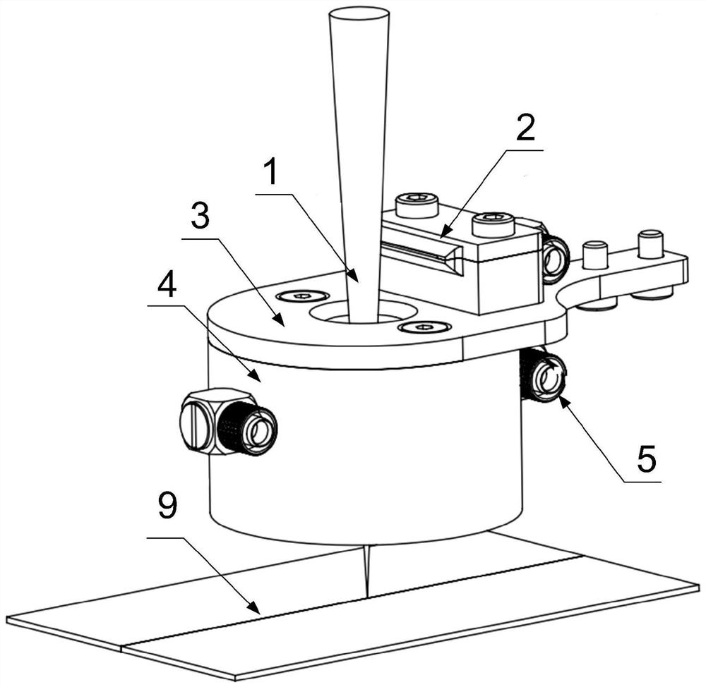
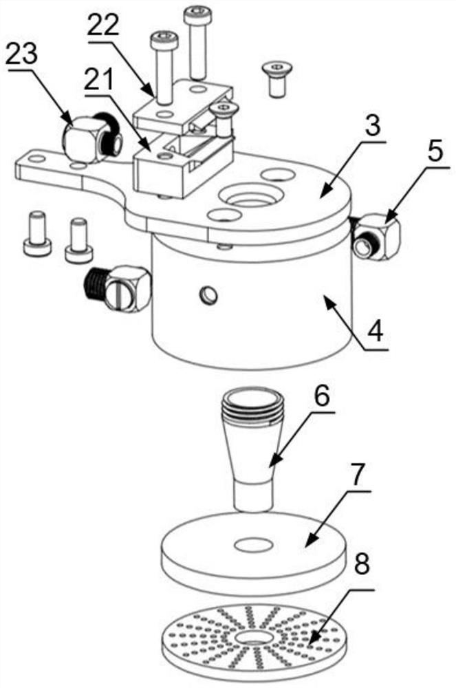
[0035] see Figure 1-5 , a shielding gas device for laser welding, including an air knife assembly 2, a connecting bracket 3, an air cavity 4, an air cavity trachea joint 5, a high temperature resistant nozzle 6, a gas homogenizing filter plate 7, and an air flow guide plate 8.

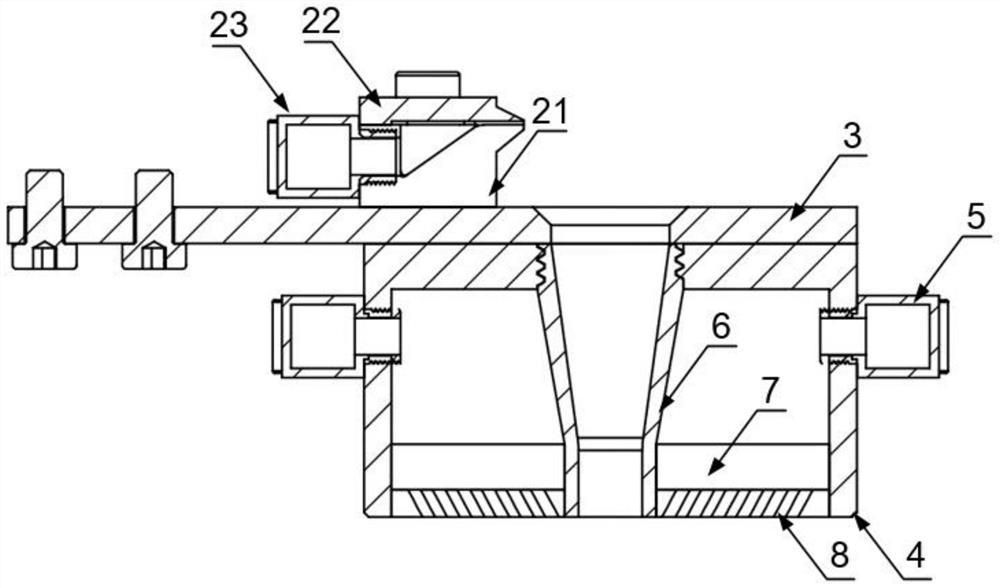
[0036] Such as figure 1 As shown, the air knife assembly 2 is detachably installed on the connecting bracket 3; the air cavity 4 is a cylindrical structure with one side open, with the opening facing downwards (see image 3 ), its top is connected with the connecting bracket 3 by screws, and the outside of the air chamber 4 is provided with an air inlet, and the air inlet and the air chamber trachea joint 5 are connected by threads. Such as figure 2 , image 3 As shown, the high temperature resistant nozzle 6 is a conical cylindrical structure with upper and lower openings, the upper end of the high temperature resistant nozzle 6 is threadedly connected to the through hole in the middle of the top...


PUM


Abstract

The invention discloses a laser welding shielding gas device. The laser welding shielding gas device comprises a gas knife assembly, a connecting support, a gas cavity, a gas cavity pipe joint, a high-temperature-resistant nozzle, a gas homogenizing filter plate and a gas flow guide plate. The gas knife assembly is installed above the connecting support. The upper portion of the gas cavity is installed below the connecting support in a seamless manner. The gas homogenizing filter plate is located below the gas cavity and is in interference fit with the inner wall of the gas cavity. The gas cavity pipe joint is installed on the outer side wall of the gas cavity. The upper end of the high-temperature-resistant nozzle is in interference fit with a through hole in the middle of the top wall ofthe gas cavity. A through hole is formed in the position, facing the upper end of the high-temperature-resistant nozzle, of the connecting support. The lower end of the high-temperature-resistant nozzle is in interference fit with a through hole in the middle of the gas homogenizing filter plate. The gas flow guide plate is located below the gas homogenizing filter plate. Laser penetrates througha hollow channel of the high-temperature-resistant nozzle to weld a welding workpiece, and meanwhile, shielding gas enters the gas cavity from the gas cavity pipe joint and then penetrates through the gas homogenizing filter plate to provide a large-range shielding gas atmosphere for a weld joint. The laser welding shielding gas device can disperse photoinduced plasmas in a laser channel.

Description

technical field [0001] The invention relates to the technical field of laser welding, in particular to a laser welding shielding gas device. Background technique [0002] Laser welding is a welding method in which a high-energy laser beam is used as a heat source, and the radiation is heated to the surface of the material, and the material is melted and connected through heat conduction. Because laser welding has the advantages of high precision, high efficiency, small heat-affected zone, and small deformation, it has a good development prospect. With the continuous development of laser technology and numerical control technology, laser welding has become an advanced processing method in the field of industrial plate welding. [0003] In the laser welding process of high-performance materials titanium alloy, aluminum alloy, stainless steel and other metal alloy materials used in aerospace and medical applications, in order to avoid the high-temperature weld seam from being ...

Claims


Application Information

Patent Timeline
Patent Type & Authority Applications(China)
IPC IPC(8): B23K26/12B23K26/21
CPCB23K26/12B23K26/21
Inventor 苏哲唐选赵磊王波鹏王瑜英
Owner 四川中久大光科技有限公司
Why Eureka
Try Eureka