
State-changing element operating device, range changing device for automatic transmission, and parking apparatus

a technology of automatic transmission and operating device, which is applied in mechanical equipment, gearing control, transportation and packaging, etc., to achieve the effect of improving operation stability and simple techniqu

Inactive Publication Date: 2010-11-25
TOYOTA JIDOSHA KK
View PDF4 Cites 16 Cited by
  • Summary
  • Abstract
  • Description
  • Claims
  • Application Information

AI Technical Summary

Benefits of technology

[0044]According to the operating device for the state-changing element according to the present invention, it is possible to, for example, position a detent member by precisely changing it to a target position with a relatively simple technique, and contribute to an improvement in operation stability.
[0045]Since the operating device included in the range changing device for the automatic transmission according to the present invention has the above-described configuration, it is possible to precisely change the state of the manual value.
[0046]Since the operating device included in the parking apparatus according to the present invention has the above-described configuration, it is possible to precisely change the state of the parking gear.

Problems solved by technology

In general, such an actuator has play (backlash, assembly error, or the like) in the rotation direction between the rotor of the electric motor and the output shaft.

Method used


Image

  • State-changing element operating device, range changing device for automatic transmission, and parking apparatus
  • State-changing element operating device, range changing device for automatic transmission, and parking apparatus
  • State-changing element operating device, range changing device for automatic transmission, and parking apparatus

Examples


Embodiment Construction

[0059]Below is a detailed description of embodiments of the present invention with references to FIGS. 1 to 12.

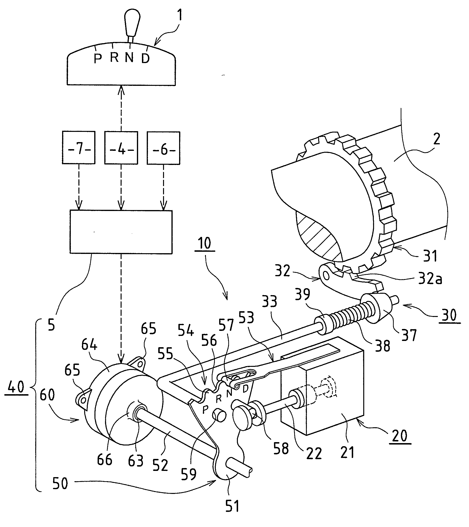
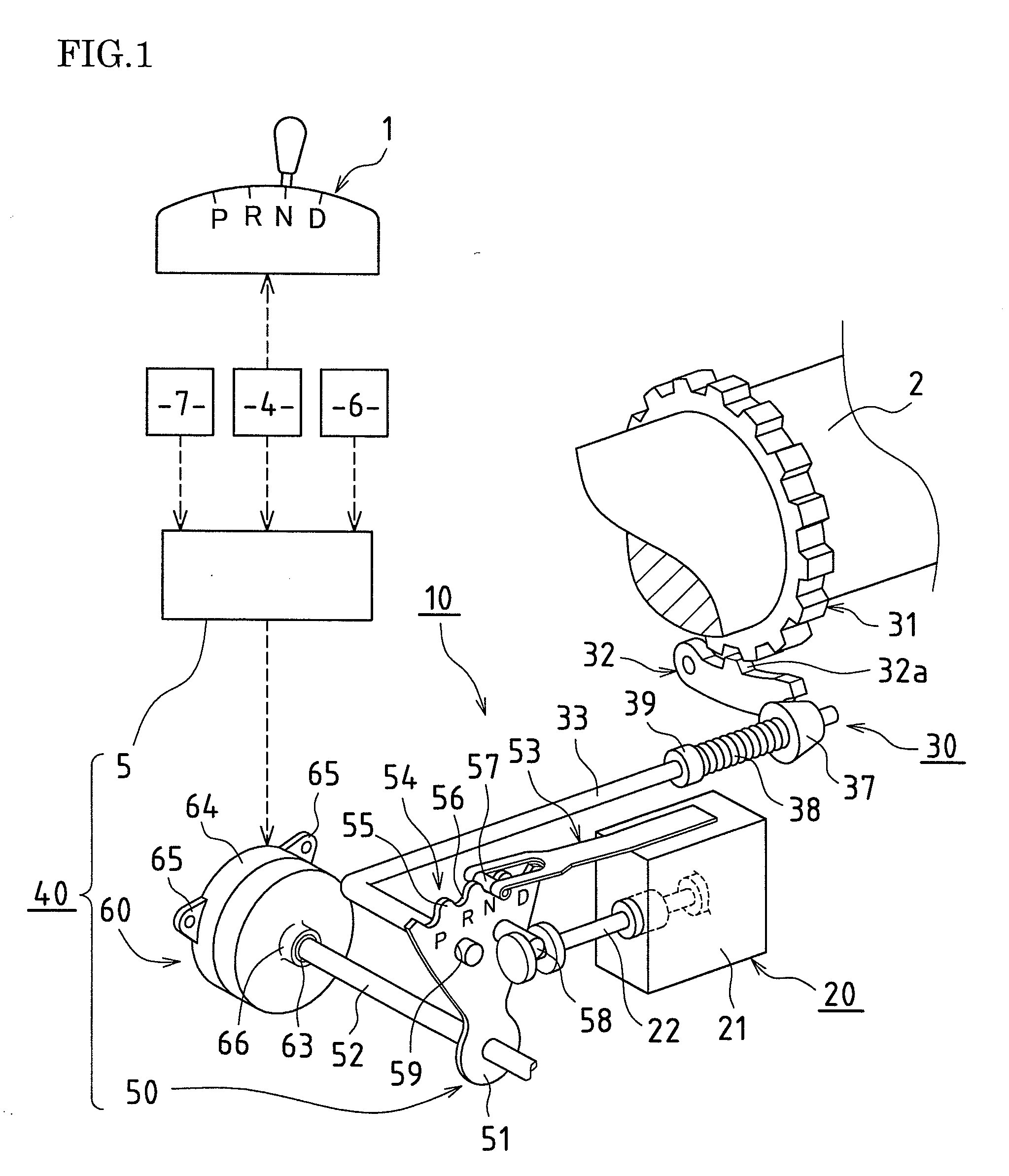
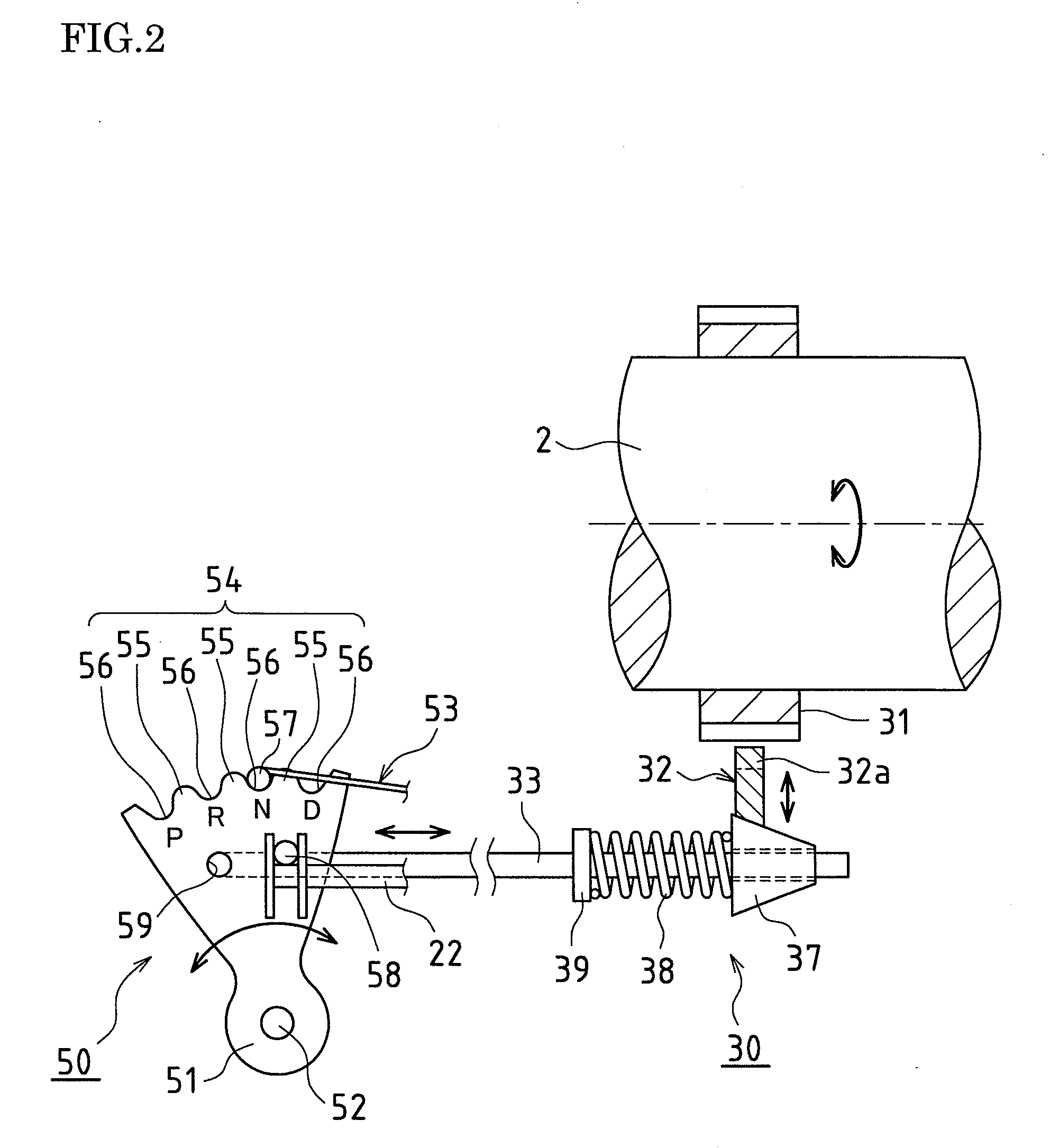
[0060]Firstly, FIGS. 1 to 8 show an embodiment of a range changing device for an automatic transmission that is a target for use of an operating device according to the present invention. Before describing portions to which features of the present invention have been applied, the following describes a schematic configuration of the range changing device with reference to FIGS. 1 to 3.

[0061]In an automatic transmission mounted in a vehicle such as an automobile, a parking range P, a reverse range R, a neutral range N, a drive range D, and the like are established according to a shift range that has been selected by, for example, a shift lever 1 as a shift operation means disposed in the vicinity of a vehicle driver seat.

[0062]A range changing device 10 of this embodiment is a so-called by-wire system, and has a configuration mainly including a manual valve 20 for range chang...


PUM


Abstract

An operating device (40) for a state-changing element that is an embodiment of the present invention includes a detent mechanism (50) for displacing and positioning displacement members (22, 33) included in a state-changing element (10), an actuator (60) for driving the detent mechanism (50), and a control unit (5) that controls the actuator (60). The control unit (5) includes an initial motion means (S1) that, in a case of receiving a request to change the state of the state-changing element (10) and changing the position of a detent member (51), drives an electric motor (61) and reduces play in the rotation direction that exists in the actuator (60), and a management means (S2 to S5) that, when it has been determined that the play has been reduced, sets a value obtained by tacking on play in the rotation direction that exists in a coupling portion between a spindle (52) and an output shaft (63) to a rotation angle necessary for a position change of the detent member (51) corresponding to the request, as a target rotation angle of the electric motor (61).

Description

TECHNICAL FIELD[0001]The present invention relates to an operating device for operating a state-changing element whose state changes by being mechanically displaced.[0002]Note that examples of a state-changing element include a range changing device for an automatic transmission mounted in a vehicle such as an automobile, and a parking apparatus disposed in a transmission for a vehicle. In other words, a range changing device, a parking apparatus, and the like are targets for use of the operating device according to the present invention.BACKGROUND ART[0003]In general, automatic transmissions for vehicles are configured such that a shift range selected from among a parking range (P), a reverse range (R), a neutral range (N), a drive range (D), and the like is established due to a driver operating, for example, a shift lever disposed in the vicinity of the driver seat of a vehicle.[0004]In general, range changing devices of recent years have been called by-wire systems, and when the ...

Claims


Application Information

Patent Timeline
Patent Type & Authority Applications(United States)
IPC IPC(8): F16H61/32
CPCF16H63/3466Y10T74/20085F16H2061/326F16H2061/247F16H2061/283F16H63/3416Y10T74/20091F16H59/08Y10T74/2003
Inventor ITAZU, NAOKINOZAKI, YOSHINOBU
Owner TOYOTA JIDOSHA KK
Learn More