Accelerator pedal apparatus

a pedal apparatus and accelerator technology, applied in the direction of mechanical control devices, instruments, process and machine control, etc., can solve the problems of insufficient responsibility, complicated configuration, and large apparatus, and achieve the effects of reducing cost, reducing excessive depression, and improving fuel consumption

a pedal apparatus and accelerator technology, applied in the direction of mechanical control devices, instruments, process and machine control, etc., can solve the problems of insufficient responsibility, complicated configuration, and large apparatus, and achieve the effects of reducing cost, reducing excessive depression, and improving fuel consumption

US20100294074A1Inactive Publication Date: 2010-11-25MIKUNI CORP

Image

  • Accelerator pedal apparatus
  • Accelerator pedal apparatus
  • Accelerator pedal apparatus

Examples


Embodiment Construction

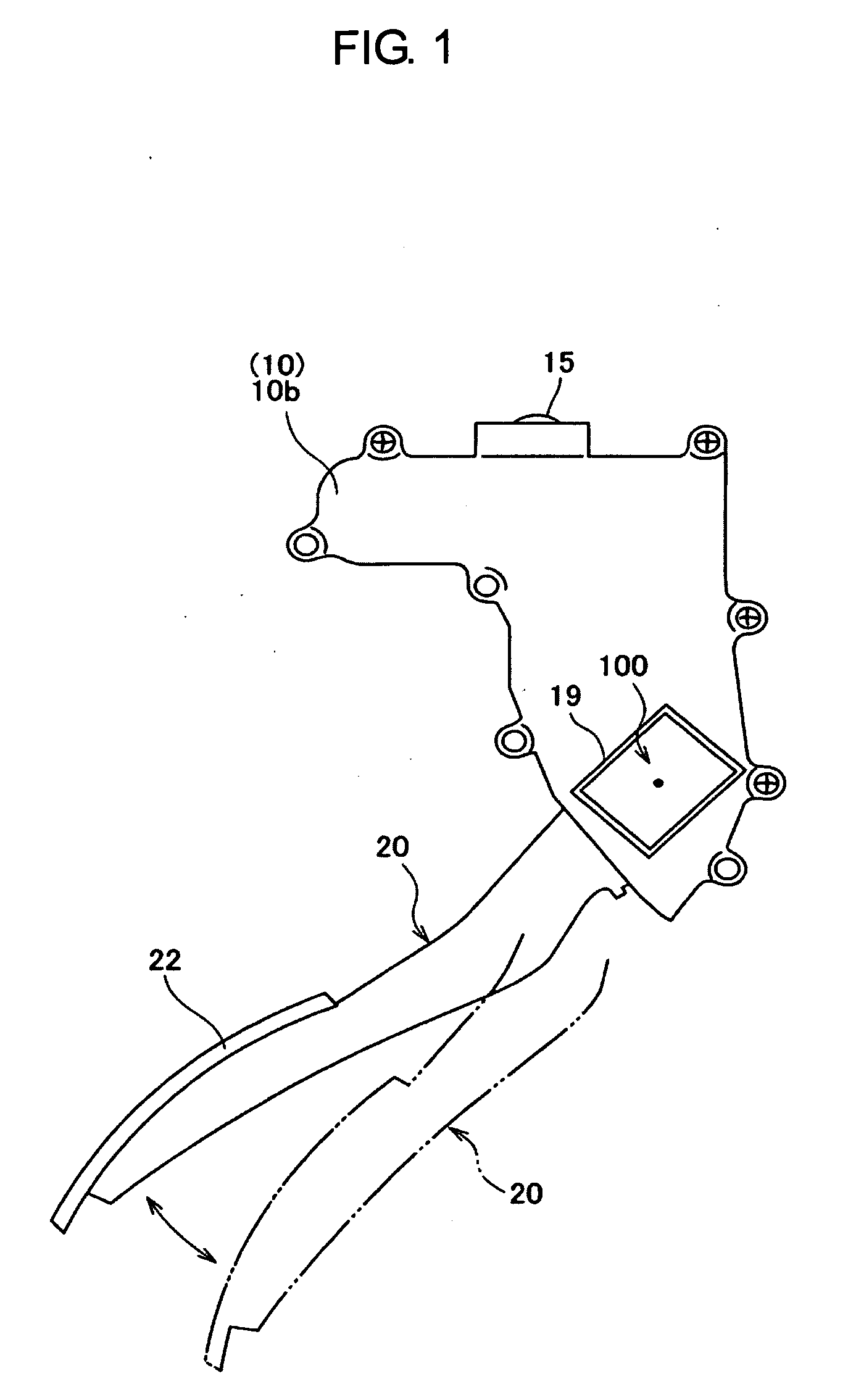
[0037]Reference will now be made in detail to the embodiments, examples of which are illustrated in the accompanying drawings, wherein like reference numerals refer to like elements throughout.

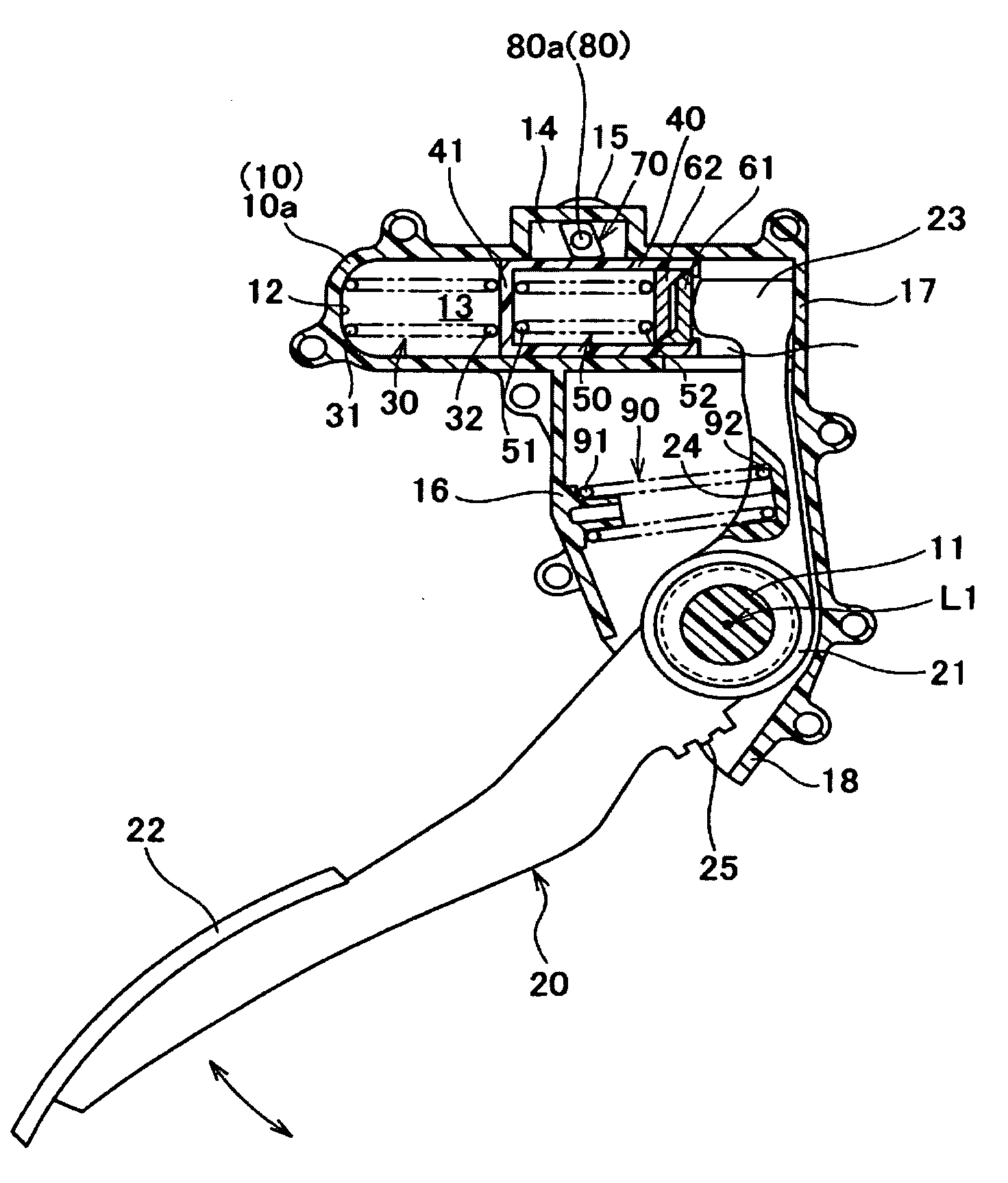
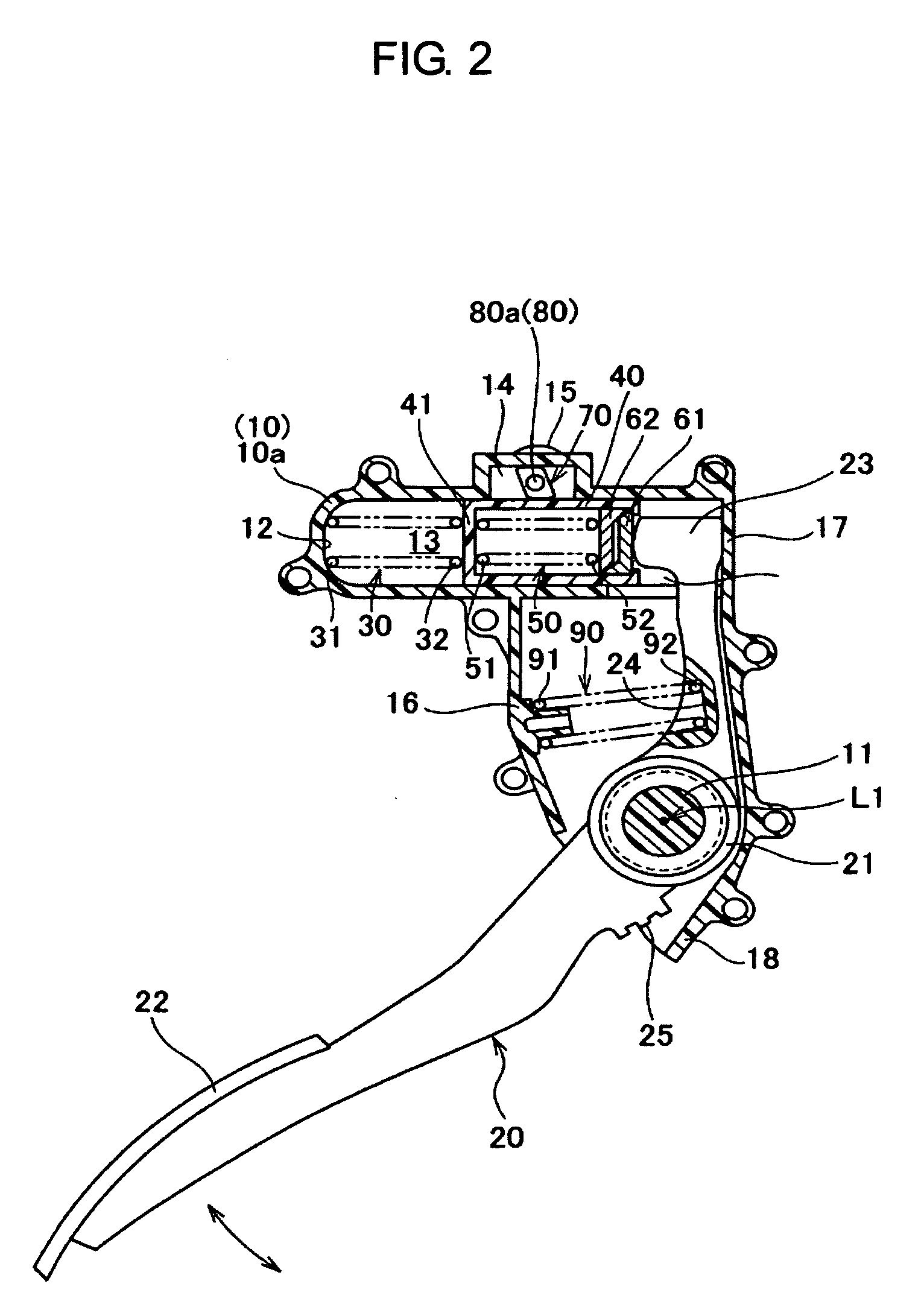
[0038]As illustrated in FIG. 1, the accelerator pedal apparatus includes a housing 10 fixed to a vehicle body of an automobile and the like, a pedal arm 20 supported swingably to the housing 10 while having an accelerator pedal 22, a first return spring 30 exerting urging force to the pedal arm 20 toward a rest position, a slider 40 as a movable member arranged slidably in a predetermined direction against the housing 10 while being contacted to the first return spring 30, a reaction force spring 50 arranged within the slider 40 being free to be compressed, inner sliders 61, 62 located between the reaction force spring 50 and the pedal arm 20 (i.e., at an upper end portion 23 thereof), a lock member 70 capable of locking the slider 40 by pressing not to be movable, an actuator 80 as a drive so...


PUM


Abstract

An accelerator pedal apparatus includes a pedal arm having an accelerator pedal, a housing rotatably supporting the pedal arm between a rest position and a maximum depression position, a first return spring exerting urging force to return the pedal arm toward the rest position, a reaction force adding mechanism adding reaction force opposed to tread force of the accelerator pedal; and the reaction force adding mechanism includes a movable member arranged movably against the housing while receiving reaction force of the first return spring, a reaction force spring arranged between the movable member and the pedal arm as being capable of generating reaction force against the tread force, and a lock mechanism being capable of locking the movable member not to be movable at desired timing, so that fuel consumption can be improved by exerting resistance force to driver's depressing operation to suppress excessive depression.

Description

CROSS-REFERENCE TO RELATED APPLICATIONS[0001]This application claims the benefit of Japanese Patent Application No. 2009-121491, filed on May 20, 2009 in the Japanese Patent Office, the disclosure of which is incorporated herein by reference.BACKGROUND[0002]1. Field[0003]The present invention relates to an accelerator pedal apparatus applied to vehicles and the like having a drive-by-wire system, and in particular, relates to an accelerator pedal apparatus including a mechanism to generate reaction force (i.e., resistance force) opposed to tread force of an accelerator pedal in order to suppress excessive depression for improving fuel consumption and the like.[0004]2. Description of the Related Art[0005]For an engine mounted on an automobile and the like, an accelerator pedal apparatus applied to an electronically controlled throttle system (i.e., a drive-by-wire system) includes a pedal arm swingably supported to a housing, a return spring to return the pedal arm to a rest position...

Claims


Application Information

Patent Timeline
25 Nov 2010
Publication
US20100294074A1
IPC
G05G1/44; G05G1/30
CPC
B60K26/021; Y10T74/20534; G05G5/03; G05G1/30; Y10T74/2054; G05G1/44
Inventors
MURAJI, TETSUO; FUKUSHIMA, YOSHITOMO