Firearm flash suppressor

a suppressor and flash technology, applied in the field of flash suppressors, can solve the problems that the flash can be detrimental to the user of the firearm, and achieve the effect of reducing the damage of the flash

Active Publication Date: 2010-11-25
COLT CANADA IP HLDG PARTNERSHIP
View PDF48 Cites 6 Cited by
  • Summary
  • Abstract
  • Description
  • Claims
  • Application Information

AI Technical Summary

Benefits of technology

[0004]The present invention is directed toward a flash suppressor that addresses one or more of the above-identified deficiencies. The firearm flash suppressor attaches

Problems solved by technology

Muzzle flash can be detrimental to a firearm user, as it can be used to locate the position of the fi

Method used


Image

  • Firearm flash suppressor
  • Firearm flash suppressor
  • Firearm flash suppressor

Examples


Embodiment Construction

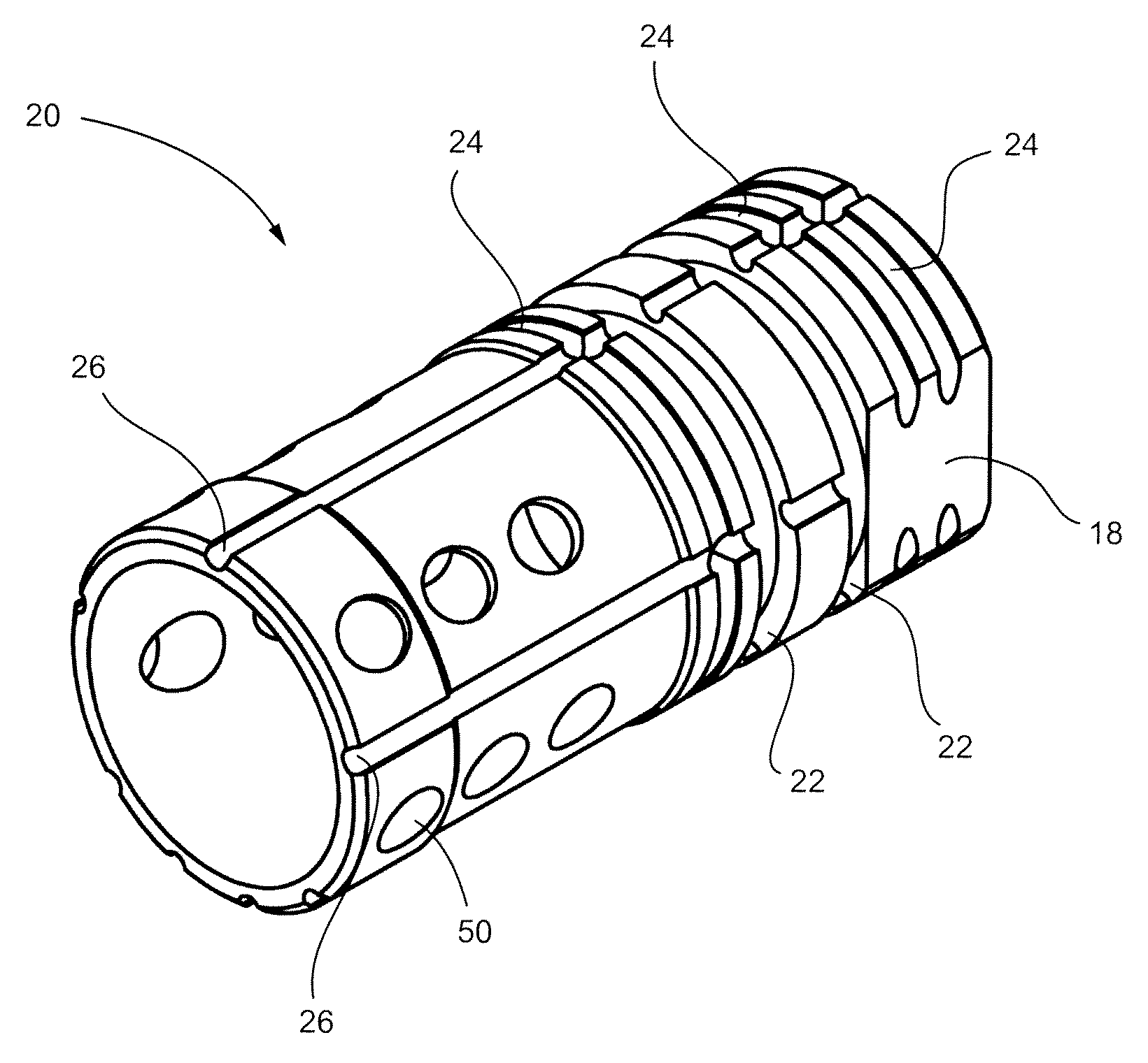
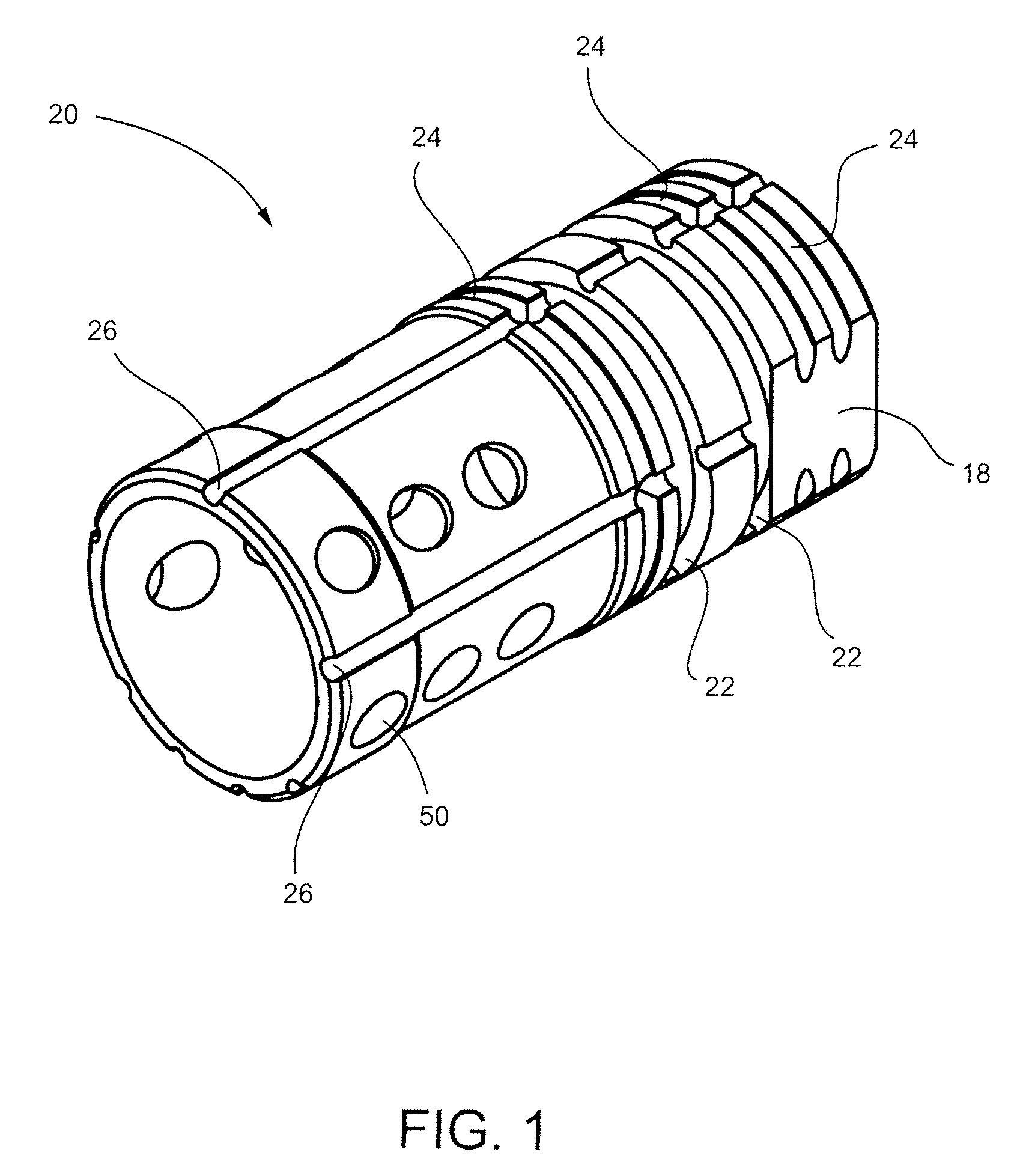
[0013]FIG. 1 shows an embodiment of a flash suppressor 20 configured for use with a standard firearm, such as a short-barrelled C9A2 Light Machine Gun, having a muzzle. Flash suppressor 20 includes a generally cylindrical body and is mounted to the muzzle, as discussed below. Attachment groove rings 22 and circumferential groove rings 24 are provided on the exterior of the cylindrical body for mounting and alignment of attachments to the flash suppressor 20. Examples of attachments include bayonets, standard blank firing attachments and noise suppressors, also know in the art as compensators.

[0014]The addition of attachments, such as a noise suppressor, may result in the build up of carbon, copper, and other materials between the flash suppressor and the attachment after repeated discharges. Longitudinal grooves 26 provide a channel for this debris to evacuate, preventing buildup of the debris and facilitating subsequent removal of the attachment.

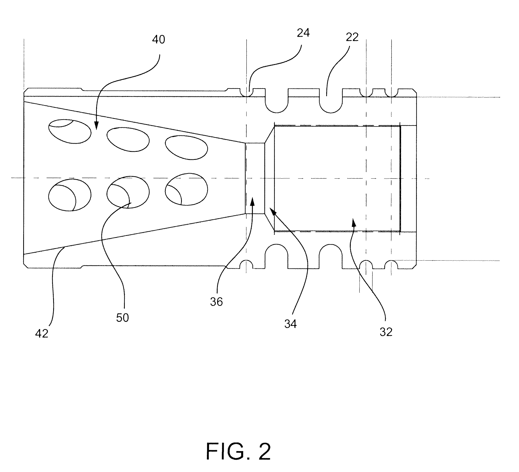
[0015]As shown in FIG. 2, the flash ...


PUM


Abstract

There is provided a flash suppressor for use with a firearm to attenuate muzzle flash. The flash suppressor can be used in conjunction with attachments, and provides mounting and alignment means therefore. In an embodiment, the flash suppressor comprises: a generally cylindrical body having a longitudinal axis, a muzzle end, and an exit end; a passage extending through the body and along the longitudinal axis; and a set of apertures. The passage includes: a mount portion for mounting the flash suppressor to the firearm muzzle; a transition portion; an intermediate portion; and a truncated conical portion having a diameter that increases toward the exit end. The transition portion joins the mount portion and the intermediate portion, and the intermediate portion joins the transition portion and the truncated conical portion. The apertures extend through the body of the flash suppressor and into the truncated conical portion, and channel propellant gases.

Description

FIELD OF THE INVENTION[0001]The present application relates generally to firearms or projectile launching devices. More particularly, the present invention relates to a flash suppressor for reducing the muzzle flash that results from the discharge of a firearm or projectile launching device.BACKGROUND OF THE INVENTION[0002]The discharge of a firearm produces high temperature propellant gases, which rapidly expand into the surrounding air as they exit the muzzle of the firearm. The propellant gases often carry residual, unburned propellant powder, which may ignite when it mixes with the oxygen-rich ambient air. The resulting combustion produces a flash of light, known as muzzle flash. Muzzle flash can be detrimental to a firearm user, as it can be used to locate the position of the firearm user and may interfere with the firearm's sighting system, particularly in low-light conditions.[0003]A variety of flash suppressors, also known as flash hiders or flash eliminators, have been deve...

Claims


Application Information

Patent Timeline
IPC IPC(8): F41A21/34
CPCF41A21/34F41A21/26
Inventor HORTOBAGYI, THOMAS
Owner COLT CANADA IP HLDG PARTNERSHIP
Why Eureka
Try Eureka