Method and device for precipitating impurities from a stream of gas

a technology of gas stream and precipitation method, which is applied in the direction of electrode construction, external electric electrostatic seperator, electric supply technique, etc., can solve the problems of low efficiency, device is not suitable for effective cleaning, and device operates in a non-homogeneous way and thus ineffectively

Inactive Publication Date: 2010-11-25
WOCO INDTECHN
View PDF15 Cites 15 Cited by
  • Summary
  • Abstract
  • Description
  • Claims
  • Application Information

AI Technical Summary

Benefits of technology

[0019]In one embodiment of the device according to the invention, the tips forming the emission electrode (cathode) are arranged in several rows, which are situated one after the other in the direction of flow of the gas to be cleaned. The tips of each row are offset, preferably laterally, in relation to the tips of the next row. As a result, there is an overlapping of the direct current plasma in the direction of flow, a state that in turn results in the space between the electrodes being practically filled with this direct current plasma, thus preventing any gaps from remaining open in the direction of flow.
[0020]Therefore, the emission electrode can be designed expediently as an emission tip array and can appear as a grid, which eliminates gaps in the plasma formed between the electrodes for a selected flow cross section of the gas stream in the direction of motion of the particles. The respective next row of tips is arranged so as to be offset by a fraction of the basic grid width. When there is an adequate number of such rows of tips that are arranged one after the other in the direction of flow, the result is a desired closed plasma arrangement in the direction of flow so that the targeted cleaning can take place by a relatively short route even in the case of a high flow rate.
[0021]It is advantageous if, in at least one embodiment of the device according to the invention, in use, a direct voltage that is higher than the breakdown voltage is applied between the electrodes and, if a device for current limiting is provided at the active electrode(s).

Problems solved by technology

In view of the flow rate of the gas to be cleaned, this device is not suitable for effective cleaning because of its limited length.
In addition, there is a considerable risk of fouling the wire electrode, which may result in the device operating in a non-homogeneous way and thus ineffectively.
The result is low efficiency and a long path is required for the actual separation, especially if the flow rate of the gas conveying the particles is high.

Method used


Image

  • Method and device for precipitating impurities from a stream of gas
  • Method and device for precipitating impurities from a stream of gas
  • Method and device for precipitating impurities from a stream of gas

Examples


Embodiment Construction

[0035]In the following description of the embodiments, those parts that exhibit identical functions have identical reference numerals, even if the shape of these parts is somewhat different.

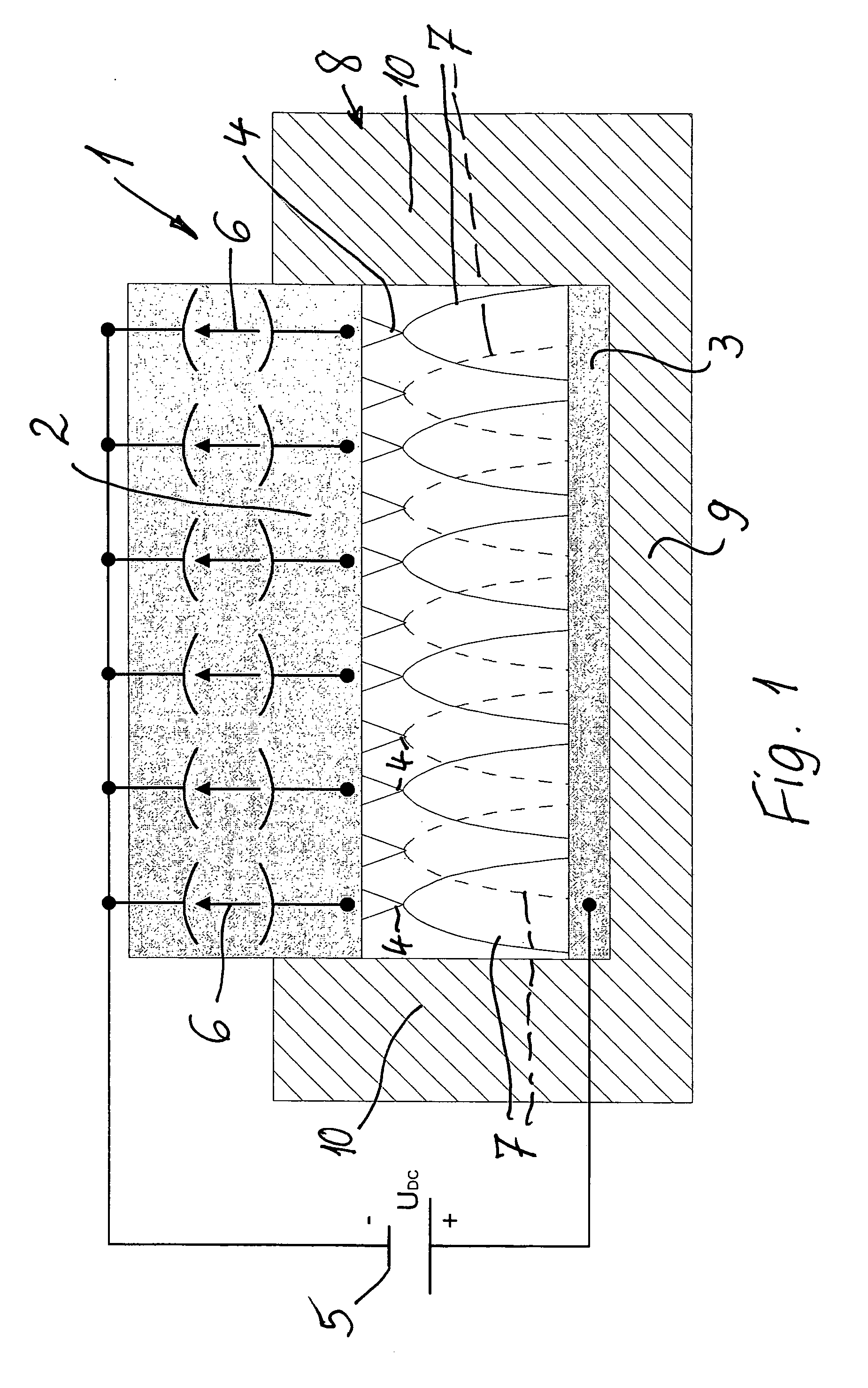
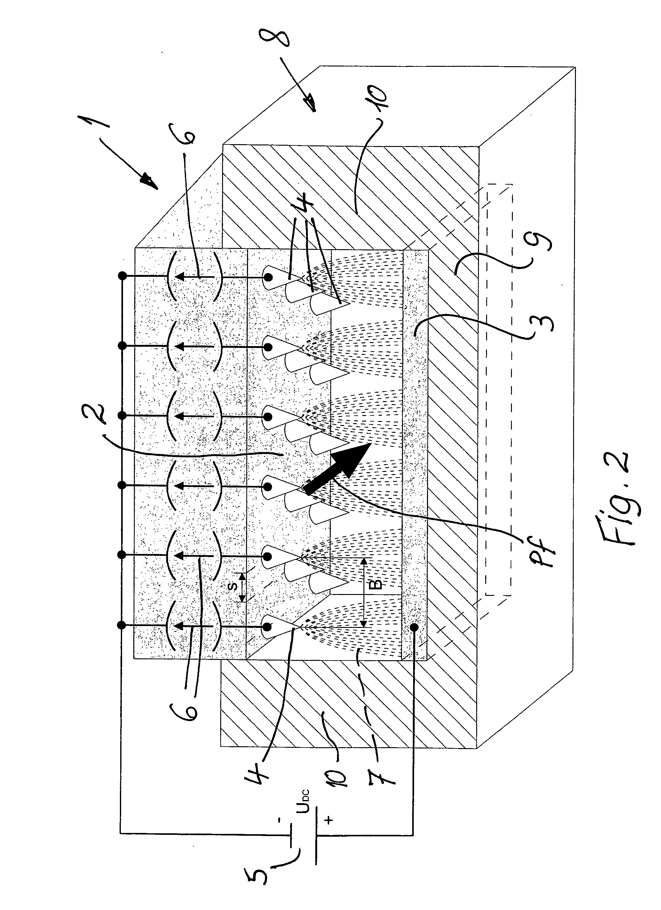
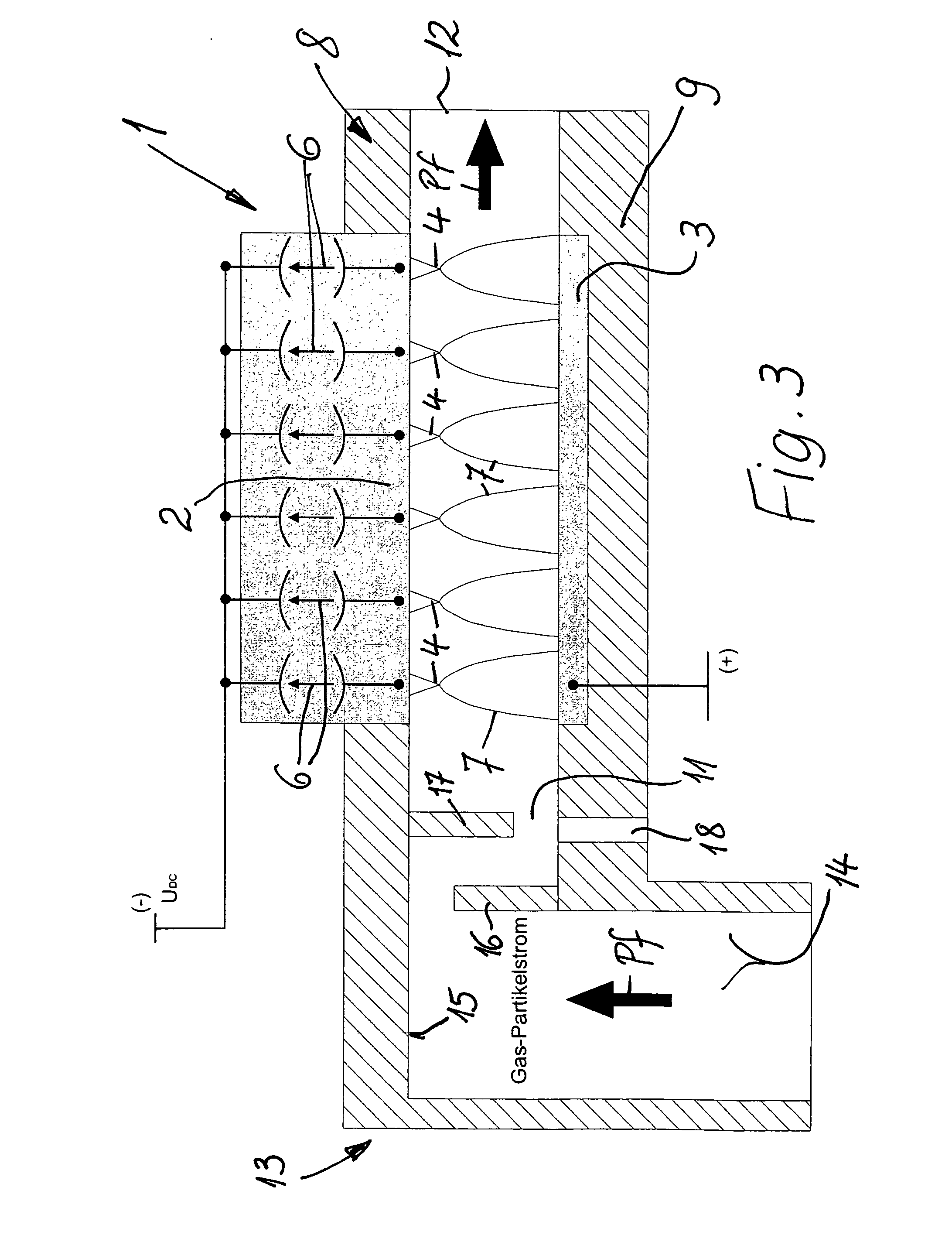
[0036]A device, which is labeled with the reference numeral 1 in all three figures, serves for precipitating liquid and / or particle-shaped impurities from a stream of gas, which is indicated by the arrow Pf in FIGS. 2 and 3. In at least one particular embodiment, the precipitation of oil droplets, soot particles, and / or dust, for example, from a stream of gas, which originates from the crankcase of an internal combustion engine and which is directed to the intake side of the internal combustion engine is concerned.

[0037]To this end, the device 1 exhibits two electrodes which are spaced apart from each other, in all of the embodiments between which the flow path of the gas stream Pf runs, wherein one of the electrodes is an active or emission electrode 2 or cathode and the other electrode is a pre...


PUM


Abstract

Liquid and/or particle-shaped impurities are precipitated from a stream of gas, for example, from a stream of gas that originates from a crankcase of an internal combustion engine and is directed to the engine's intake side. The stream of gas is passed through a gas discharge section between two electrodes. The stream of gas is passed between an emission electrode which is formed by electrode tips and an opposing electrode at a distance therefrom. A direct voltage which exceeds the breakdown voltage is applied to the electrodes using a direct current high voltage source, and the current which occurs over the gas discharge section between the electrodes is limited. A stable low energy direct current plasma is formed in the space between the two electrodes. The impurities are electrically charged and attracted to the opposing electrode by means of electrical field forces.

Description

FIELD OF DISCLOSURE AND INTRODUCTION[0001]The present disclosure relates to a method for precipitating liquid and / or particle-shaped impurities from a stream of gas, for example, for precipitating oil droplets, soot particles, and / or dust from a stream of blow-by gas that originates from a crankcase of an internal combustion engine and is directed to the intake side of the internal combustion engine. In this context, the stream of gas that is to be cleaned is passed through a gas discharge section between at least two electrodes, of which at least one electrode is an active or emission electrode (cathode) and at least one other electrode is a precipitation or counter-electrode (anode), by means of which the impurities to be precipitated from the stream of gas are electrically charged and sucked in or attracted by the counter-electrode by means of electrical field forces.[0002]The present disclosure further relates to a device for precipitating liquid and / or particle-shaped impuritie...

Claims


Application Information

Patent Timeline
Patent Type & Authority Applications(United States)
IPC IPC(8): B03C3/41B03C3/40B03C3/011
CPCB03C3/41B03C3/68B03C2201/30B03C2201/10B03C2201/06
Inventor OP DE LAAK, MARCELKNOPF, FRANZ
Owner WOCO INDTECHN
Why Eureka
Try Eureka