Solar Module with a Frame for Mounting a Solar panel

a solar module and solar panel technology, applied in the direction of solar heat collector mounting/support, solar heat collector safety, light and heating apparatus, etc., can solve the problems of frame failure damage to solar panel, etc., and achieve the effect of increasing the structural rigidity of solar module and efficiently making

Inactive Publication Date: 2010-11-25
BP CORP NORTH AMERICA INC
View PDF33 Cites 50 Cited by
  • Summary
  • Abstract
  • Description
  • Claims
  • Application Information

AI Technical Summary

Benefits of technology

[0015]Optionally, the frame may include a sealant along at least a portion of the frame, the flange and / or the solar panel. The sealant keeps out water and may increase the structural rigidity of the solar module.
[0016]The span element may form a connection channel along at least a portion of the length of the frame member for receiving or sliding at least a portion of an anchor into the member and attaching it to the structure. The connection channel can provide installation without the need to drill additional holes in and / or through the frame, for example, to compensate for misalignment from an uneven roof. The connection channel may prevent axial rotation of the anchor, such as by holding a head of anchor against a wall or other suitable structure to engage the anchor.
[0017]The members of the frame may include at least one attachment boss on or within the frame members for receiving at least one fastener, such as a tapered screw. Attachment bosses help to join or mate frame members, such as at butt joints or lap joints forming corners of the solar panel. Butt joints can be efficiently made during fabrication and installation.

Problems solved by technology

The wind and the snow loads can damage the solar panel.
The load on the panel may cause the frame to fail when a portion of the solar panel comes out of or disengages the frame due to the twisting or spreading of the frame.
This failure also often damages the solar panel requiring replacement of the solar panel.
Structures, such as rooftops, are not always uniform have irregularities which require added installation steps, for example, drilling additional holes in the frame to mount the solar module.

Method used


Image

  • Solar Module with a Frame for Mounting a Solar panel
  • Solar Module with a Frame for Mounting a Solar panel
  • Solar Module with a Frame for Mounting a Solar panel

Examples


examples

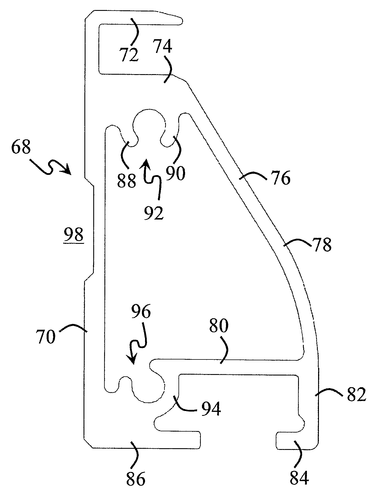
[0093]Frame 10, according to certain embodiments of this invention, with extruded member 68, as shown in FIG. 6, was subjected to physical testing along with a conventional solar module frame having an open channel design. The results for wind loading are summarized in Table 1 and show significantly increased performance by frame 10 versus the conventional design.

TABLE 1PressureVertical DeflectionLateral Width2400 Pa(mm)Increase (mm)Conventional−16.011.5Improvement−13.50.5

[0094]Similarly, the overall solar module 14 strength according to certain embodiments of this invention was tested to successfully withstand loads of at least 6240 Pa and thereby exceeded the IEC 61215, Second edition standard of 5400 Pa. The testing of module 14, according to certain embodiments of this invention with extruded member 68 as shown in FIG. 6, had an at least about 2.6 times increase in overall module strength compared to the conventional solar module having an open channel frame design.


PUM


Abstract

This invention relates to a frame for mounting a solar panel where a tubular frame member has a generally triangular cross section. The frame member includes a riser element, a span element and a truss element. 5 The frame meets the IEC 61215, Second edition standard for wind and snow loadings without significantly increasing the weight of the solar module compared to conventional frames with an open channel. This invention also relates to an array of solar modules mounted on a structure as well as a method of mounting the frame with a connection channel for slidably accepting an anchor.

Description

[0001]This patent application claimed the benefit of U.S. Provisional Patent Application Ser. No. 60 / 944,863, filed on Jun. 19, 2007.BACKGROUND OF THE INVENTION[0002]1. Field of the Invention[0003]This invention relates to solar module frames for mounting solar panels to a structure.[0004]2. Discussion of Related Art[0005]Solar technology seeks to convert energy from the sun into electricity and reduce demands on conventional sources of electricity, such as fossil fuels. The need for renewable energy sources exists in areas with temperate climates as well as areas with winter climates. Solar cells convert sunlight into direct current. Typically, multiple solar cells are positioned between substrate plates or sheets, one of which is transparent to light, and the plates with the solar cells there between formed into solar panels. Such solar panels are usually of a convenient size for handling and for mounting on a roof or other structure, and such panels are typically rectangular in s...

Claims


Application Information

Patent Timeline
Patent Type & Authority Applications(United States)
IPC IPC(8): H01L31/048F16M13/00
CPCF24J2/4614F24J2/464F24J2/5203F24J2/5211H02S20/00F24J2002/5215F24J2002/5224Y02E10/47Y02E10/50F24J2002/4658F24S25/30F24S80/40F24S25/20F24S2025/806F24S25/60F24S2025/801F24S40/44
Inventor CUNNINGHAM, DANIEL W.DUPONTE, KAI H.W.PLACER, NEIL V.PARR, ANDY E.DUNCAN, ROYEBNER, SEIGFRIED
Owner BP CORP NORTH AMERICA INC
Why Eureka
Try Eureka