Airless, Chainless Bicycle

a chainless bicycle and airless technology, applied in the field of bicycles, can solve the problems of no specialty bicycles that are reliable in harsh working environments, no maintenance, work bikes that wear out quickly, etc., and achieve the effects of avoiding wires and other easily degradable components, being easily operable by several different users, and carrying safely small loads

Inactive Publication Date: 2010-11-25
DENAIS VINCE
View PDF16 Cites 19 Cited by
  • Summary
  • Abstract
  • Description
  • Claims
  • Application Information

AI Technical Summary

Benefits of technology

[0012]The objective of the present invention is to provide a novel chainless bicycle that is well-suited for use in harsh environments. In line with this objective, the bicycle of the present invention has a drive assembly that contains a drive shaft and has airless tires which cannot go flat. Additionally, the bicycle of the present invention has a coaster brake, which eliminates the need for wires and other easily degradable components associated with hand brakes. Furthermore, the bicycle has a frame and metal components that are coated, making them rust resistant.
[0013]It is a further objective of the present invention to provide an airle

Problems solved by technology

Despite the variety of specialty bicycles available, there are no specialty bikes that are reliable in harsh working environments, tailored for use by multiple riders, and require little to no maintenance.
With years of wear-and-tear, work bikes are usually old, rusted, chain driven bicycles with traditional air-inflated tires.
This type of environment causes the work bikes wear out quickly and ultimately leads to failure of the bicycle parts and possibly, injury accidents.
For example, the chains often rust quickly causing them to “kink” or break during use.
Rust also affects the frame of the bicycle—especially where the paint is chipped—and the frame may become too brittle to support a rider.
Furthermore, the component parts of the bicycle, such as the hand brakes or sprockets, also rust in the extreme environments.
With hand brakes, the rust often causes the brakes to stick or the cables to snap.
Traditional chain-driven bicycles are not well-suited to be work bikes.
In addition to worn parts and regular maintenance, loose pant legs get caug

Method used


Image

  • Airless, Chainless Bicycle
  • Airless, Chainless Bicycle
  • Airless, Chainless Bicycle

Examples


Embodiment Construction

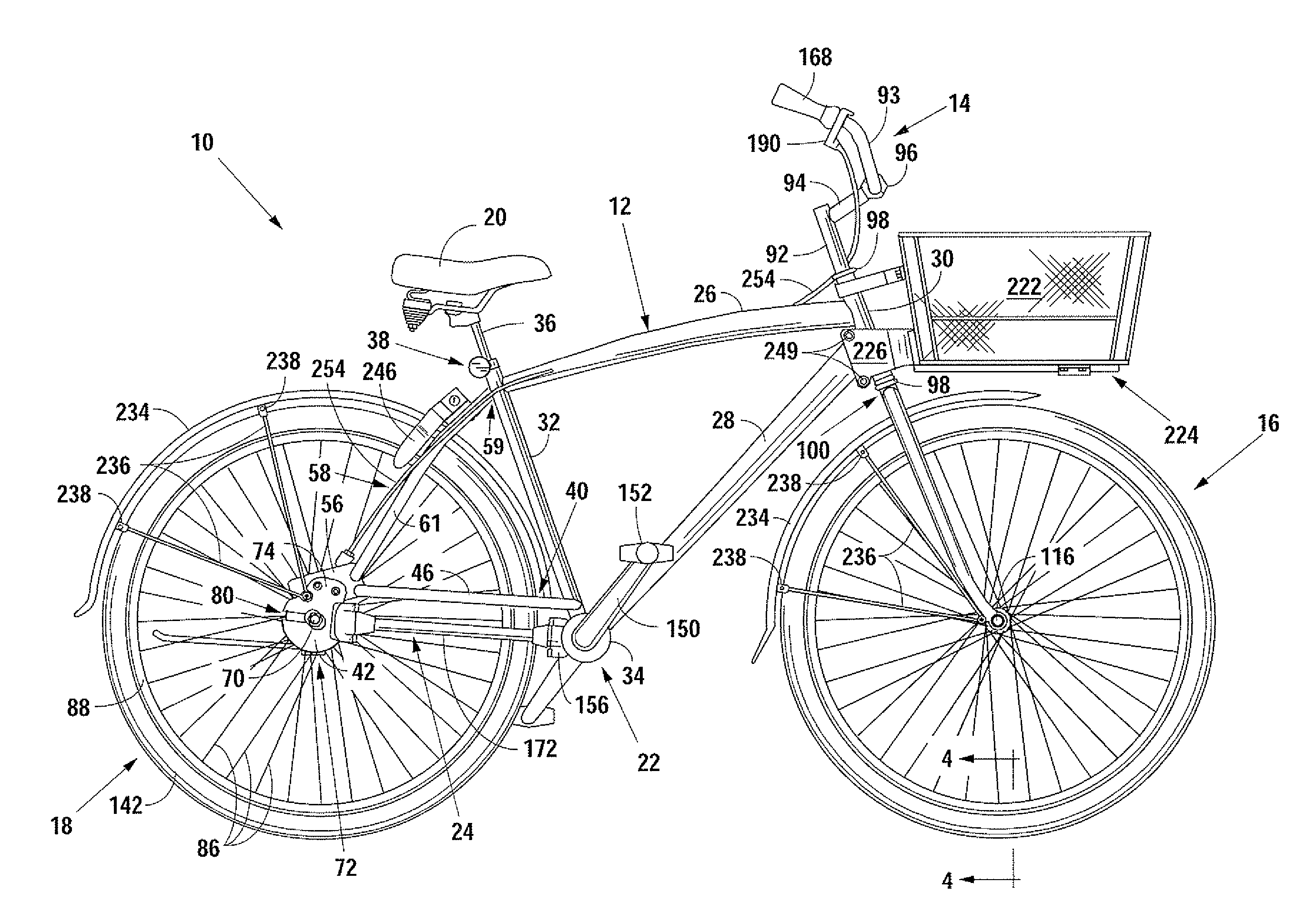
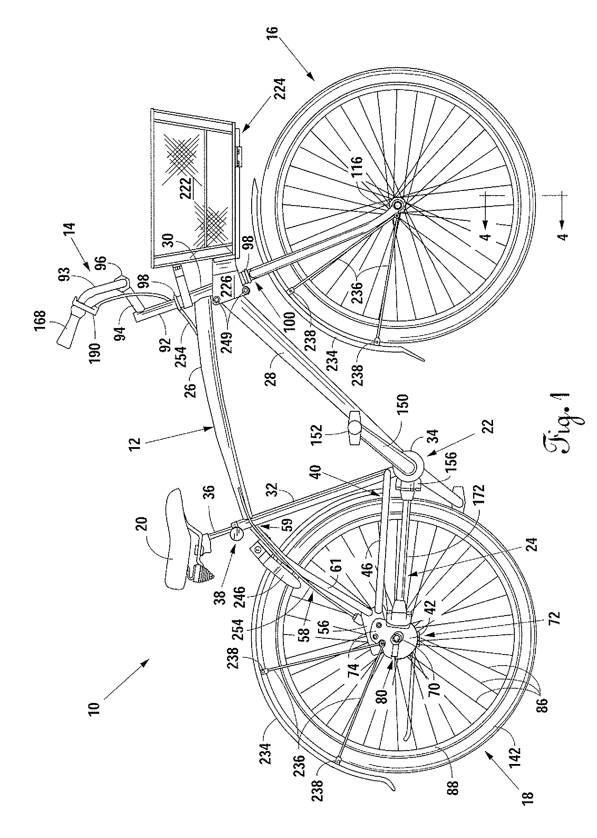
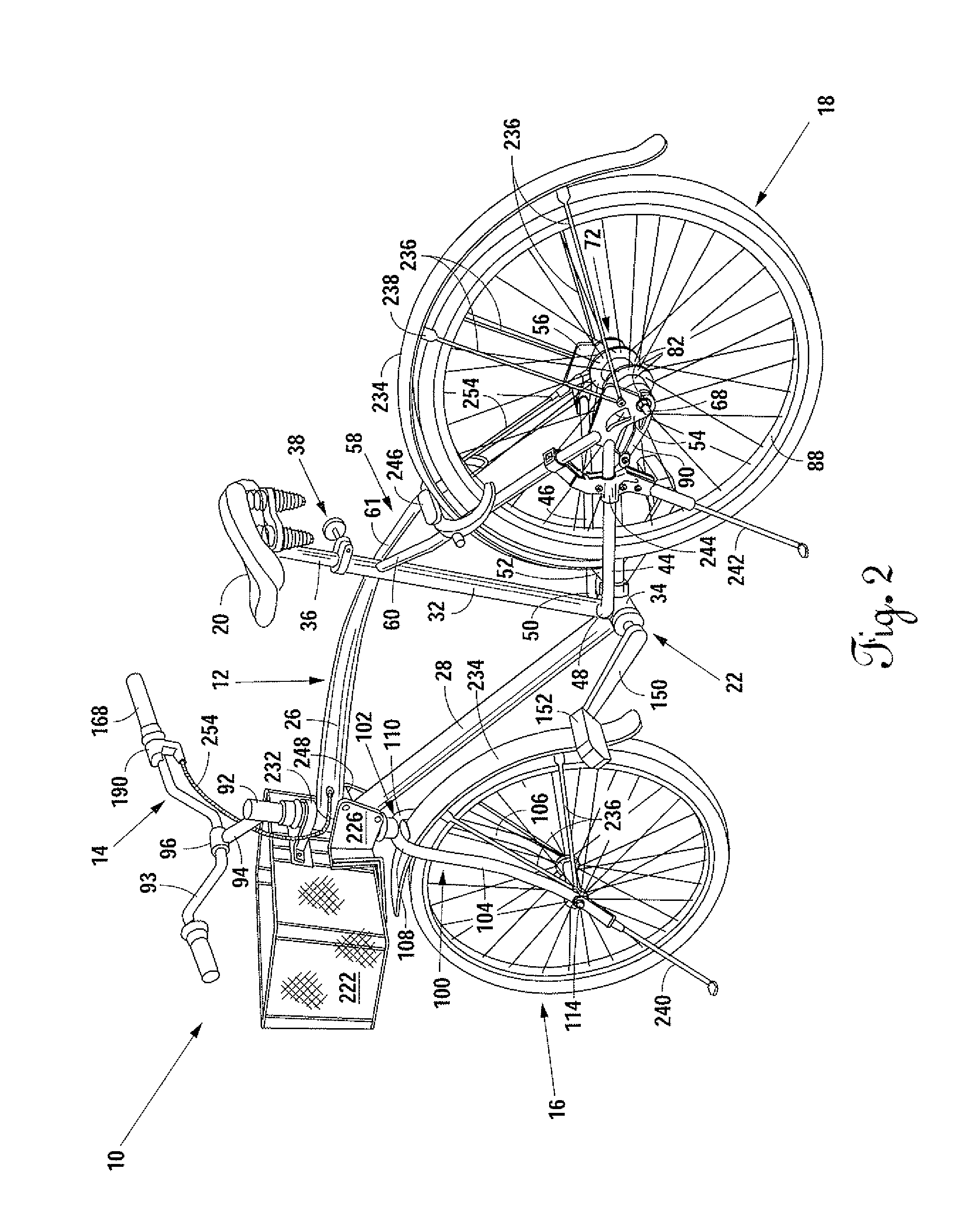
[0029]The preferred embodiment of a bicycle 10 of present invention is illustrated in FIGS. 1 and 2. In its most basic elements, the bicycle 10 has a frame 12 with a handle bar assembly 14, a front wheel 16, a rear wheel 18, a seat 20, a pedal assembly 22, and a drive assembly 24, which are all somehow directly or indirectly attached to the to the frame 12, as described in further detail herein.

[0030]The frame 12 has an upper frame member 26, a lower frame member 28, a front frame member 30, a rear frame member 32, and a bottom bracket 34. Beginning at the front frame member 30, the upper frame member 26 connects to and extends from the front frame member 30 toward the rear of the bicycle 10 and terminates where it is connected to the rear frame member 32. The lower frame member 28 is positioned below the upper frame member 26, and, is connected to and extends from the front frame member 30 at a downward angle toward the pedal assembly 22. The lower frame member 28 terminates at and...


PUM


Abstract

A durable, airless, chainless bicycle multiple riders of differing heights is disclosed. The bicycle is propelled by a drive shaft instead of a chain, making the drive assembly more dependable. The tires are made from a solid material and cannot go flat. The frame and other components of the bicycle are either inherently rust resistant or are coated to increase their rust resistance. The bicycle also has a front basket that is mounted such that the basket does not turn when the front wheel turns. Finally, the bicycle has a seat adjustment mechanism which allows the seat height to be adjusted without tools.

Description

BACKGROUND OF THE INVENTION[0001]1. Field of the Invention[0002]The present invention generally relates to bicycles. More specifically, the invention relates to a bicycle that has a combination of features making it low maintenance and that is resistant to the wear-and-tear caused by harsh environments and frequent use. The present invention discloses a bicycle that is propelled by a drive shaft, has solid, airless tires, and rust resistant metal components.[0003]2. Background Information[0004]Bicycles have been used as a mode of transportation and recreation for centuries. Bicycles have a variety of purposes—from racing down the streets of France and mountain biking up the Rocky Mountains to making deliveries in the city. As bicycle technology advanced and bicycles evolved, different types of bicycles emerged which are tailored to the specific activities for which the bicycle is used. Today there are road bikes, mountain bikes, triathlon bikes, racing bikes, dirt bikes, tandem bike...

Claims


Application Information

Patent Timeline
IPC IPC(8): B62M1/06B60C7/00B62J1/00B62K3/02B60W10/18
CPCB60C7/10B60C7/24B60Y2200/12Y10T152/10396B62K19/36B62M17/00B60C2200/12B62J9/003B62J9/21
Inventor DENAIS, VINCE
Owner DENAIS VINCE
Why Eureka
Try Eureka