LED bar

a technology of led bars and led connectors, applied in the direction of lighting and heating apparatus, instruments, lighting support devices, etc., can solve the problems of increasing the risk of current jumps and ground faults, corrosion of electrical circuits, and dangerous ground faults, and achieves efficient cooling of leds, high efficiency, and easy connection

Active Publication Date: 2010-11-25
MARTIN PROFESSIONAL
View PDF14 Cites 123 Cited by
  • Summary
  • Abstract
  • Description
  • Claims
  • Application Information

AI Technical Summary

Benefits of technology

[0004]It is the object of the invention to achieve a highly efficient LED bar for generating a bar of light. A further object is to form modules of a LED bar which are easy to connect and which by connection automatically connect both power and data. A third object of the invention is to achieve efficient cooling of the LEDs. Yet another object is to achieve an efficient electrical isolation between

Problems solved by technology

The circuit for high voltage power lines runs through the interior of the housing and there is thus a great risk that current might jump from the high voltage and power lines to the housing causing dangerous ground faults.
This risk is increased when the LED housing is used in moist and humid environments (e.g. on a cruse ship where the LED housing might get in contact with saltwater)

Method used


Image

  • LED bar
  • LED bar
  • LED bar

Examples


Embodiment Construction

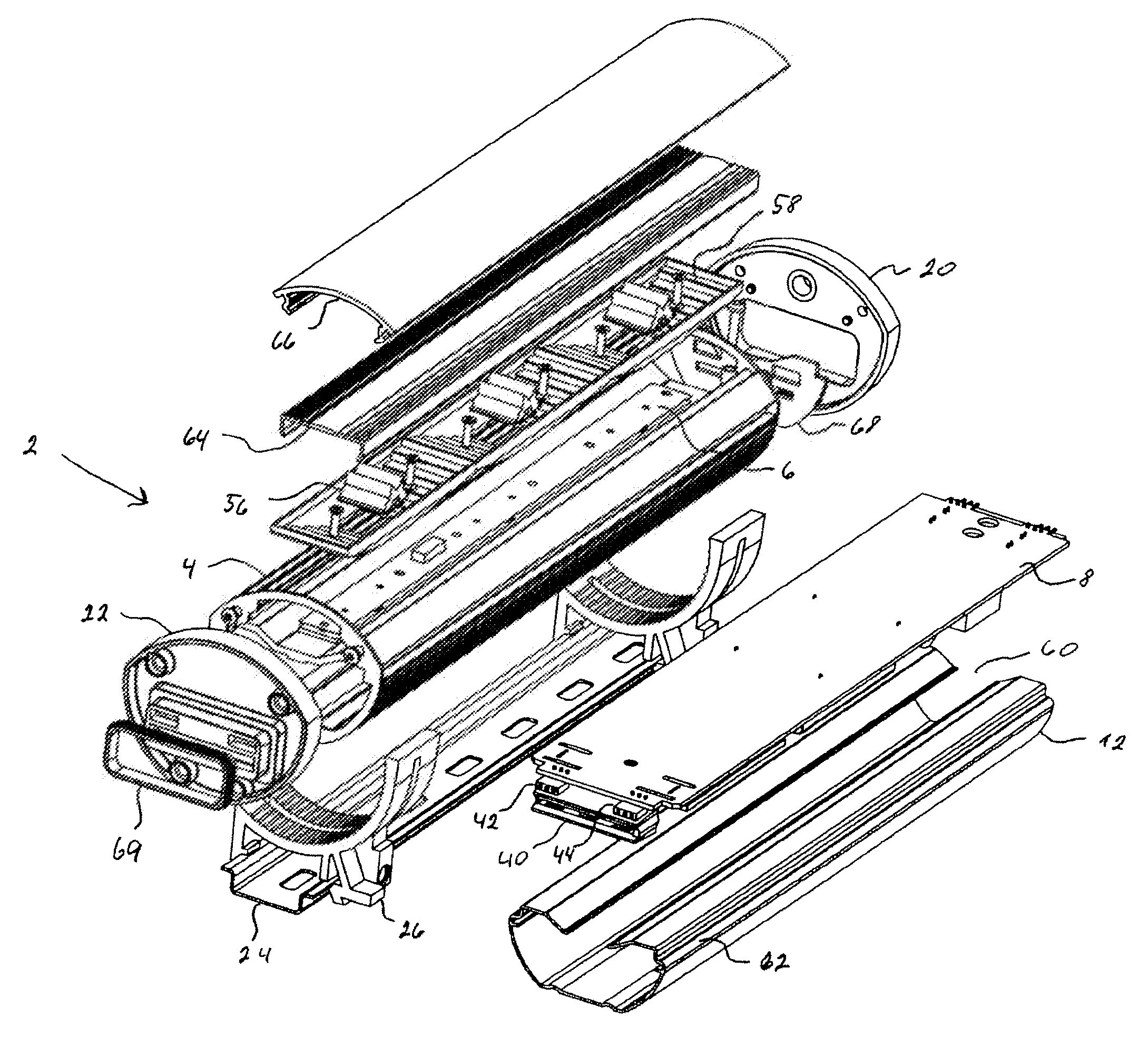
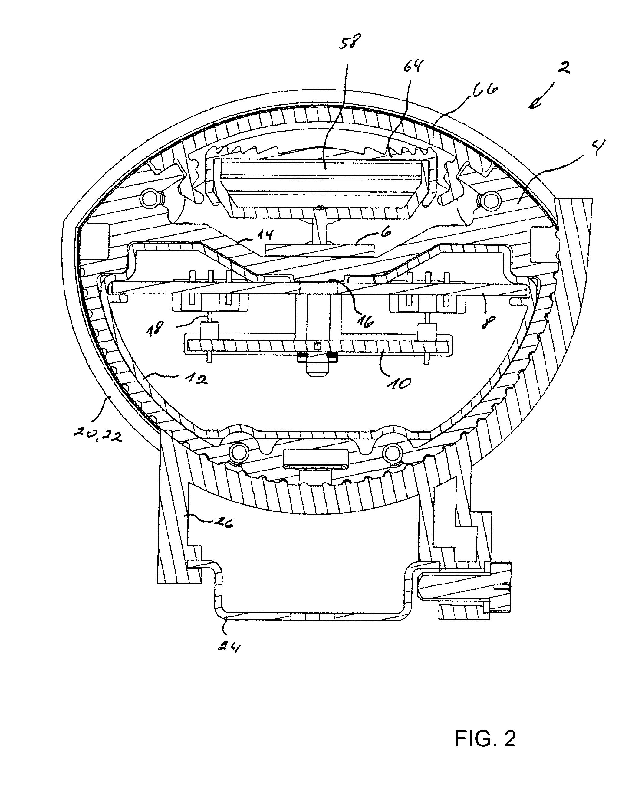
[0005]The object of the invention can be fulfilled with a LED bar module as described in the preamble to claim 1 if the main printed circuit is placed inside a heat conductive tube, where the pixel board is placed outside the heat conductive tube in a longitudinal recess, where a connector is electrically connecting the pixel board to the main printed circuit, where the main printed circuit is placed inside an isolation cover, which isolation cover is placed between the main printed circuit and the heat conductive tube, which isolation cover has a longitudinal opening for achieving heat conduction between the main printed circuit and a central part of the upper wall of the heat conductive tube.

[0006]Hereby, it is achieved that the LEDs are placed on the outside of the tube in a way where heat generated from the LEDs is conducted downwards to the tube. Inside the tube, the rest of the power electronics and also the light controlling electronics are placed. Placing e.g. switch mode, s...


PUM


Abstract

The present invention relates to LED bar modules where the LED groups are placed at a pixel board. The present invention further concerns a method for calibration of LEDs. It is the object of the invention to achieve a highly efficient LED bar for generating a bar of light. A further object of the invention is to store calibration data for each LED both electrically and mechanically close to the actual LED. Preferably, the main printed circuit is placed inside a heat conductive tube, where the pixel board is placed outside the heat conductive tube in a longitudinal recess, where the main printed circuit is placed inside an isolation cover. Hereby, it is achieved that the LEDs are placed on the outside of the tube in a way where heat generated from the LEDs is conducted downwards to the tube. Inside the tube, the rest of the power electronics and also the light controlling electronics are placed.

Description

FIELD OF THE INVENTION[0001]The present invention relates to LED bar modules comprising a number of LED groups, which LED groups comprise a number of LEDs, which LEDs have different colours, which LEDs are electrically connected to a colour controller for generating light of changing colour, which colour controller is connected to a power supply, which is formed as a main printed circuit (8), where the LED groups are placed at a pixel board, which pixel board conducts heat from the LEDs.[0002]The present invention further concerns a method for calibration of LEDs, where the LEDs are connected to control means, which control means control at least one electric parameter used in relation to the operation of the LEDs, where each LED is connected to its own control circuit.BACKGROUND OF THE INVENTION[0003]U.S. 2006 / 0002110 disclose a linear LED housing comprising a top part attached to a bottom part by fasteners. The power and data are fed through the interior of the lighting unit and t...

Claims


Application Information

Patent Timeline
IPC IPC(8): H05B37/02F21V29/00H05B44/00
CPCF21S4/008F21S10/02F21V5/045F21V13/04F21V23/06F21V29/004F21V29/83F21V31/03F21Y2101/02H05B33/0803H05B33/0857F21V29/74F21V29/2206F21S4/28F21Y2115/10F21V21/30F21Y2103/10F21V29/507H05B45/20H05B45/00
Inventor PEDERSEN, ALLANCHEN, XIALI, GUOHUILIANG, CHEN
Owner MARTIN PROFESSIONAL
Why Eureka
Try Eureka