Gradient sensor of a component of a magnetic field with permanent magnet

a technology of magnetic field and gradient sensor, which is applied in the direction of magnetic measurement, instruments, measurement devices, etc., can solve the problems of limiting the sensitivity of the gradient measurement, affecting the measurement of the other sensor, and affecting the accuracy of the gradient measuremen

Inactive Publication Date: 2010-11-25
COMMISSARIAT A LENERGIE ATOMIQUE ET AUX ENERGIES ALTERNATIVES +1
View PDF4 Cites 31 Cited by
  • Summary
  • Abstract
  • Description
  • Claims
  • Application Information

AI Technical Summary

Benefits of technology

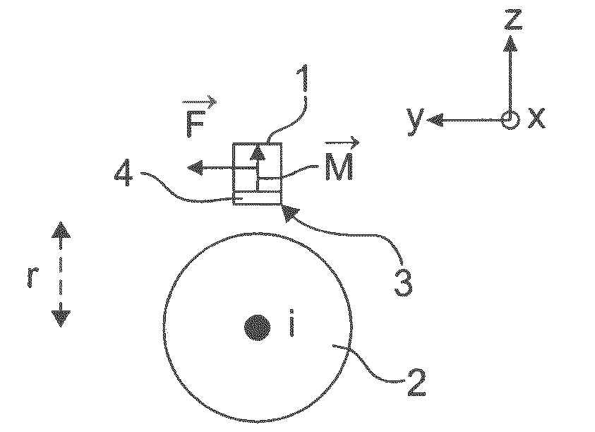
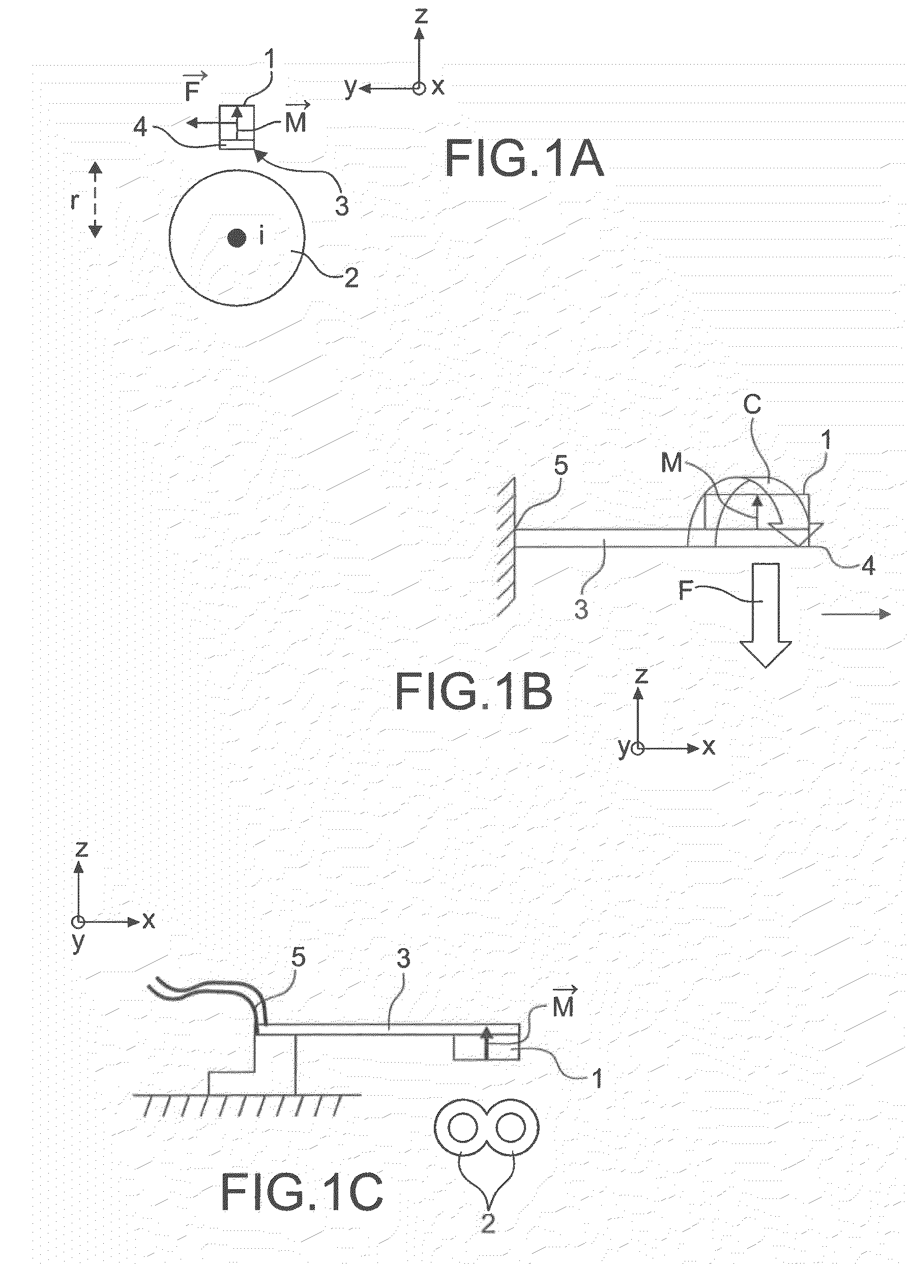
[0038]To achieve this, the present invention proposes placing the magnet on a deformable mass able to deform under the effect of a force exerted on the magnet by the gradient, the effect of this force being to shift the magnet in a direction substantially colinear to the component of the magnetic field for which the sensor has to acquire the gradient, the deformable mass being anchored in at least two points substantially opposite relative to the deformable mass to a fixed device support, the magnet having a magnetization direction which is substantially colinear to the direction of the gradient of the component of the magnetic field which the sensor has to acquire.
[0039]More precisely, the present invention is a gradient sensor of a component of a magnetic field comprising at least one elementary sensor comprising a deformable mass equipped with a permanent magnet having a magnetization direction substantially colinear to the direction of the gradient of the component of the magnetic field to be acquired by the sensor. The deformable mass is able to deform under the effect of a force exerted on the magnet by the gradient, the effect of this force being to shift it, by dragging the deformable mass, in a direction substantially colinear to the component of the magnetic field for which the sensor has to acquire the gradient. The deformable mass is anchored to a fixed support device in at least two anchoring points substantially opposite relative to the mass. The elementary sensor also comprises measuring means of at least one electric variable translating deformation or stress of the deformable mass engendered by the gradient.

Problems solved by technology

But the presence of the magnetic circuit of one of the sensors can perturb the measuring of the other sensor and vice versa.
Also, precision of the gradient measuring is limited by precision of the two sensors, by precision of the knowledge of their positions and by the reproducibility of the properties of each of the sensors taken individually.
This document eliminates the disadvantages associated with the presence of both sensors but precise measuring of the position is always required, which limits the sensitivity of the measuring of the gradient.
The disadvantage of this sensor is that it consumes electricity relatively substantially.
Using optical fiber does not produce a sensor on the micrometric scale via collective technologies of microelectronics or microelectromechanics.
A disadvantage of the structure described in document [5] and that described in document [4] is that, when the magnet is subjected to a magnetic field which is not colinear to its magnetization direction, it is subjected to torque which can generate parasite deformation on the beam or on the optical fiber.
This can impair measuring precision or at the very least substantially restrict the conditions of use of the detector.
The disadvantages of this device are that it is both difficult to position the permanent magnet 1 so that it is perfectly equidistant from the two wire conductors 2′ and also that the same current must circulate in both wire conductors 2′.
In the event of a difference, measuring the magnetic field gradient will be unreliable.

Method used


Image

  • Gradient sensor of a component of a magnetic field with permanent magnet
  • Gradient sensor of a component of a magnetic field with permanent magnet
  • Gradient sensor of a component of a magnetic field with permanent magnet

Examples


Embodiment Construction

[0083]Reference is now made to FIG. 3 which shows a gradient sensor of a component of a magnetic field according to the invention. It is assumed that the magnetic field is generated by a current i3 circulating in a electric wire conductor 30 directed according to the axis y of the orthonormal marker. The gradient sensor of the component of the magnetic field comprises at least one elementary sensor CE1 comprising a deformable mass 31 equipped with a permanent magnet 32. The deformable mass 31 lays at rest in the plane x,y. The deformable mass 31 can take the form of a membrane, which means that its thickness is much less than its two other dimensions. The deformable mass 31 is able to deform under the effect of a force exerted by the magnetic field gradient, this force being applied to the magnet 32. The effect of this force is to shift the magnet 32 and the latter locally brings with it the deformable mass 31, resulting in its deformation. The shift is made in a direction substanti...


PUM


Abstract

A gradient sensor of a component of a magnetic field comprising at least one elementary sensor comprising a deformable mass (31) equipped with a permanent magnet (32) having a magnetization direction substantially colinear to the direction of the gradient of the component of the magnetic field to be acquired by the sensor. The deformable mass (31) is able to deform under the effect of a force exerted on the magnet by the gradient, the effect of this force being to shift it, by dragging the deformable mass (31), in a direction substantially colinear to the component of the magnetic field for which the sensor has to acquire the gradient. The deformable mass (31) is anchored to a fixed support device (33) in at least two anchoring points (36) substantially opposite relative to the mass (31). The elementary sensor also comprises measuring means (35, 35.1, 35.2, 35.3) of at least one electric variable translating deformation or stress of the deformable mass (31) engendered by the gradient.

Description

TECHNICAL FIELD[0001]The present invention concerns a sensor of the gradient of a component of a magnetic field and a production process of this sensor in integrated technology. With respect to the magnetic field, it can be magnetic excitation H also called current field or magnetic induction B, these two variables being connected in a fixed manner.[0002]Such a sensor can be utilised for taking measurements without contact from current circulating in a filiform conductor. The fields of application of such current measuring are numerous. They can be especially evaluation of electric consumption in buildings, whether industrial or domestic, in terrestrial, maritime or aerial transport means. Another field is for example the protective function by tripping circuit breakers of electrical installations in the same environments. It can also be employed to ensure protection of electric motors, the costly copper windings of which must not be penetrated by excessive electric currents which d...

Claims


Application Information

Patent Timeline
Patent Type & Authority Applications(United States)
IPC IPC(8): G01R33/02H01L21/30
CPCG01R33/022G01R33/0286G01R33/028
Inventor WALTHER, ARNAUDCUCHET, ROBERTDELAMARE, JEROMEMSAED, ALINEALBERTINI, JEAN-BAPTISTE
Owner COMMISSARIAT A LENERGIE ATOMIQUE ET AUX ENERGIES ALTERNATIVES
Why Eureka
Try Eureka