Determinate and indeterminate optical systems

a technology of optical systems and indeterminate optical systems, applied in the field of optical systems, can solve the problems of inability to include moving parts, optical systems that provide high quality focusing and aberration control are typically expensive to design and manufacture, and achieve the effect of reducing the peak breaking the mtf of the optical system

Inactive Publication Date: 2010-11-25
DIGITALOPTICS CORPORATION
View PDF15 Cites 14 Cited by
  • Summary
  • Abstract
  • Description
  • Claims
  • Application Information

AI Technical Summary

Benefits of technology

[0012]In accordance with this aspect of the invention, the number of optical surfaces may be less than that of a diffraction limited optical system, and may be less than that of a conventional optical system having a peak MTF of at least 80% of that of the diffraction limited system. The selected range of object distances may define a depth of field of the optical system. Each one of the plurality of optical surfaces may contribute to broadening the MTF of the optical system. The peak MTF of the optical system may be reduced when any one of the number of optical surfaces is removed.
[0013]A further aspect of the invention provides an imaging system which includes a blurring optical system and an image sensor operable to capture light directed by said optical system and to generate raw data representing the directed li...

Problems solved by technology

However, such movement also causes objects that previously appeared in focus to now appear out-of focus.
It is not practical to include moving parts because of size and cost constraints, and thus their imaging systems have a fixed focal range.
Such optical sy...

Method used


Image

  • Determinate and indeterminate optical systems
  • Determinate and indeterminate optical systems
  • Determinate and indeterminate optical systems

Examples


Embodiment Construction

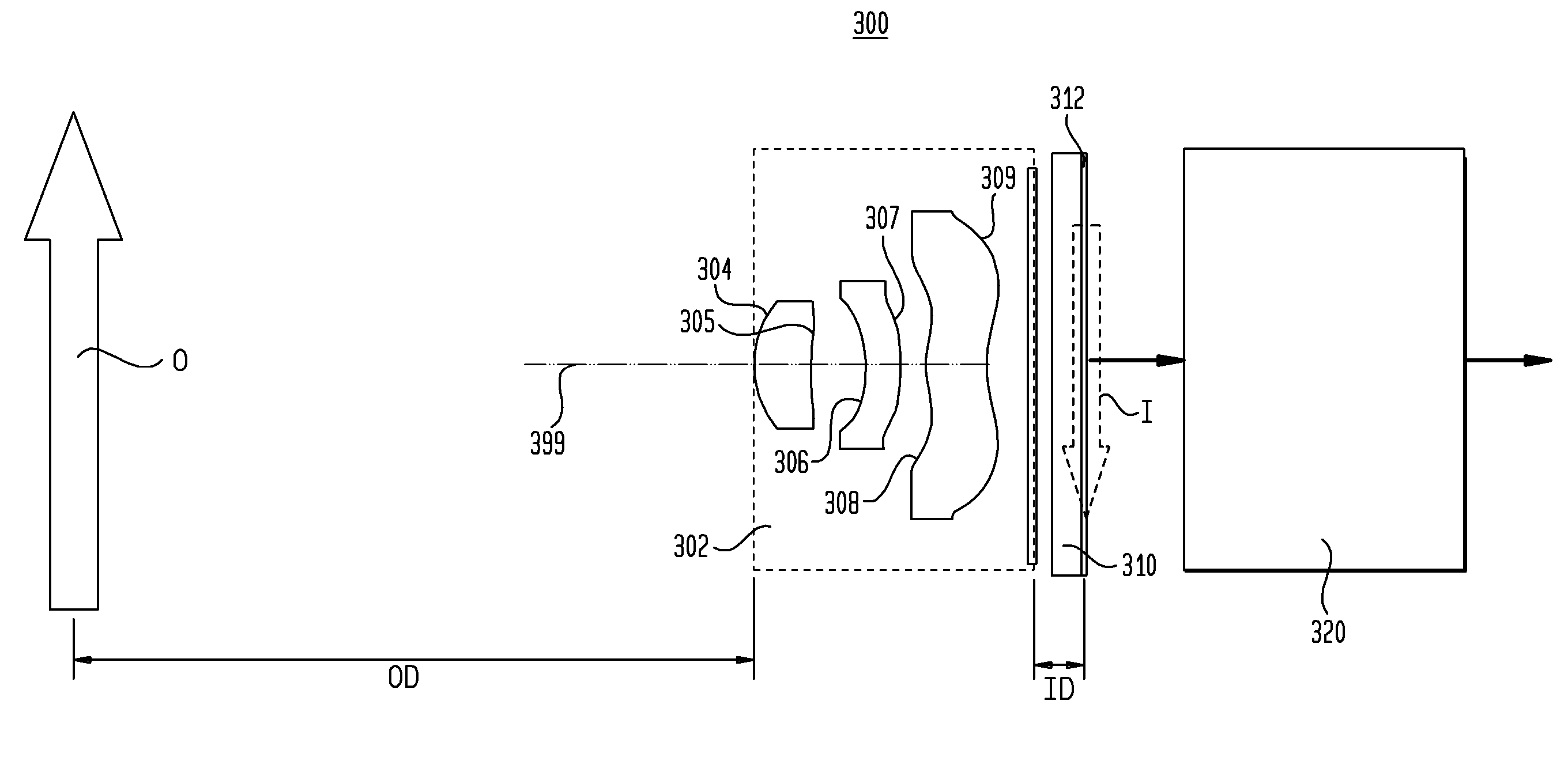
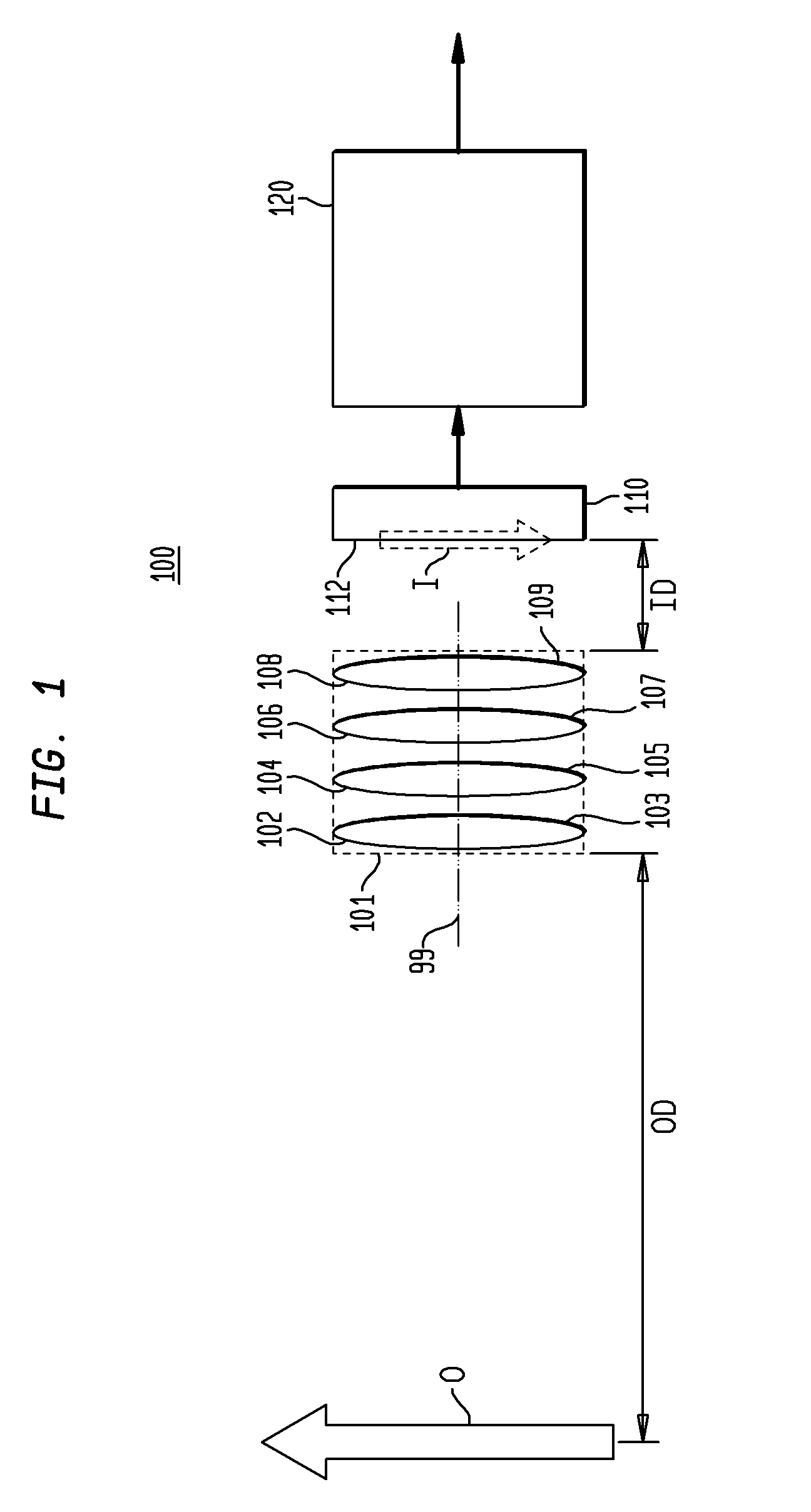
[0030]FIG. 1 is a block diagram depicting an example of a known digital imaging system 100. The digital imaging system 100 includes an optical system 101, an image sensor 110, and an image processor 120. The optical system 101 receives light that is reflected off of, or that is emitted by, an object O onto an image surface 112 of the image sensor 110. The optical system includes optical elements having surfaces 102 through 109 inclusive arranged along an optical axis 99. The object distance OD between the optical system and the object O, and the image distance ID between the optical system and the image I are distances along the optical axis 99. One of the optical surfaces 102 through 109 blurs an image directed onto the image surface 112 and the others provide for focusing of this image and for correction of chromatic or other aberrations. The blurring optical surface is typically located in the pupil plane of the optical system 101 though it is not restricted to that location. If ...


PUM


Abstract

An optical system (302) has a plurality of optical surfaces (304, 305, 306, 307, 308, 309) configured to provide blurred images of objects located within a selected range of object distances. At least two of the plurality of optical surfaces are configured to contribute to the blurring. An imaging system (300) includes a blurring optical system (302), a sensor (310) which receives light directed through the optical system, and an image processor (320) which selects one or more deblurring functions and applies the deblurring functions to provide a processed image. The processor may apply different deblurring functions to different sets of the raw data representing different portions of the field of view.

Description

CROSS-REFERENCE TO RELATED APPLICATION[0001]This application claims the benefit of the filing date of U.S. Provisional Application No. 61 / 001,988 filed Nov. 6, 2007, the disclosure of which is incorporated herein by reference.BACKGROUND OF THE INVENTION[0002]The present invention is directed to optical systems and, more particularly, to optical systems that are located at a fixed position within an imaging system and that provide a customized depth of field.[0003]In a conventional digital imaging system, light received by an optical system consisting of one or more lenses is projected onto an image plane at which an image sensor is located. The received light may be, for example, light reflected off of or light emitted by one or more objects located at various distances from the lens. The image sensor detects the image directed onto the image plane and generates raw data that is processed by an image processor which produces a processed image that is available for storage or for vie...

Claims


Application Information

Patent Timeline
IPC IPC(8): H04N5/217G02B13/20
CPCG02B13/20G06T5/003G02B27/0075
Inventor AUBUCHON, CHRISTOPHERMORRIS, JAMESKINTZ, GREGORYCARRIERE, JAMESFELDMAN, MICHAEL R.
Owner DIGITALOPTICS CORPORATION
Why Eureka
Try Eureka