
Liquid crystal display device

Inactive Publication Date: 2010-11-25
SONY CORP
View PDF5 Cites 7 Cited by
  • Summary
  • Abstract
  • Description
  • Claims
  • Application Information

AI Technical Summary

Benefits of technology

[0008]Recently, a view angle is desired to be widened with increase in size of a liquid crystal display device. To achieve a wide view angle, it is basically important to suppress change in hue depending on viewing angles as above. In addition, it is important to suppress light leakage in black display. Such light leakage causes black display to be somewhat whitish as seen in an oblique direction. The light leakage in black display is caused by slight light leakage in an oblique direction from a liquid crystal display panel.
[0010]It is desirable to provide a liquid crystal display device, in which light leakage in black display is suppressed, and change in hue depending on viewing angles is suppressed, and consequently a wide view angle may be achieved.
[0014]In the case of black display, light leakage in an oblique direction to the liquid crystal display panel is suppressed. The reason for this is as follows. In the liquid crystal display panel, when black display is performed without disposing the optical filter, leakage light in an oblique direction to a display surface has the hue having a local minimum value in the wavelength range from 450 nm to 550 nm both inclusive, for example, a somewhat reddish or yellowish hue. That is, the liquid crystal display panel acts as a kind of band-cut filter. In contrast, when the optical filter is disposed on an incident surface side of the liquid crystal display panel, oblique incident light to the panel contains a large quantity of light in a wavelength range from 400 nm to 550 nm both inclusive rather than light in another wavelength range. Therefore, when black display is performed with the optical filter being disposed, light in the wavelength range from 400 to 550 nm both inclusive being a major part of a spectrum of the oblique incident light is effectively cut by the liquid crystal display panel, resulting in suppressing light leakage in the oblique direction.

Problems solved by technology

However, Japanese Patent No. 2861982 does not disclose suppression of light leakage in black display.
Therefore, it has been hard to achieve a wide view angle by suppressing light leakage in black display while suppressing change in hue depending on viewing angles.

Method used


Image

  • Liquid crystal display device
  • Liquid crystal display device
  • Liquid crystal display device

Examples


first embodiment

1. First Embodiment

Example of VA-Mode Liquid Crystal Display Device Configuration of Liquid Crystal Display Device

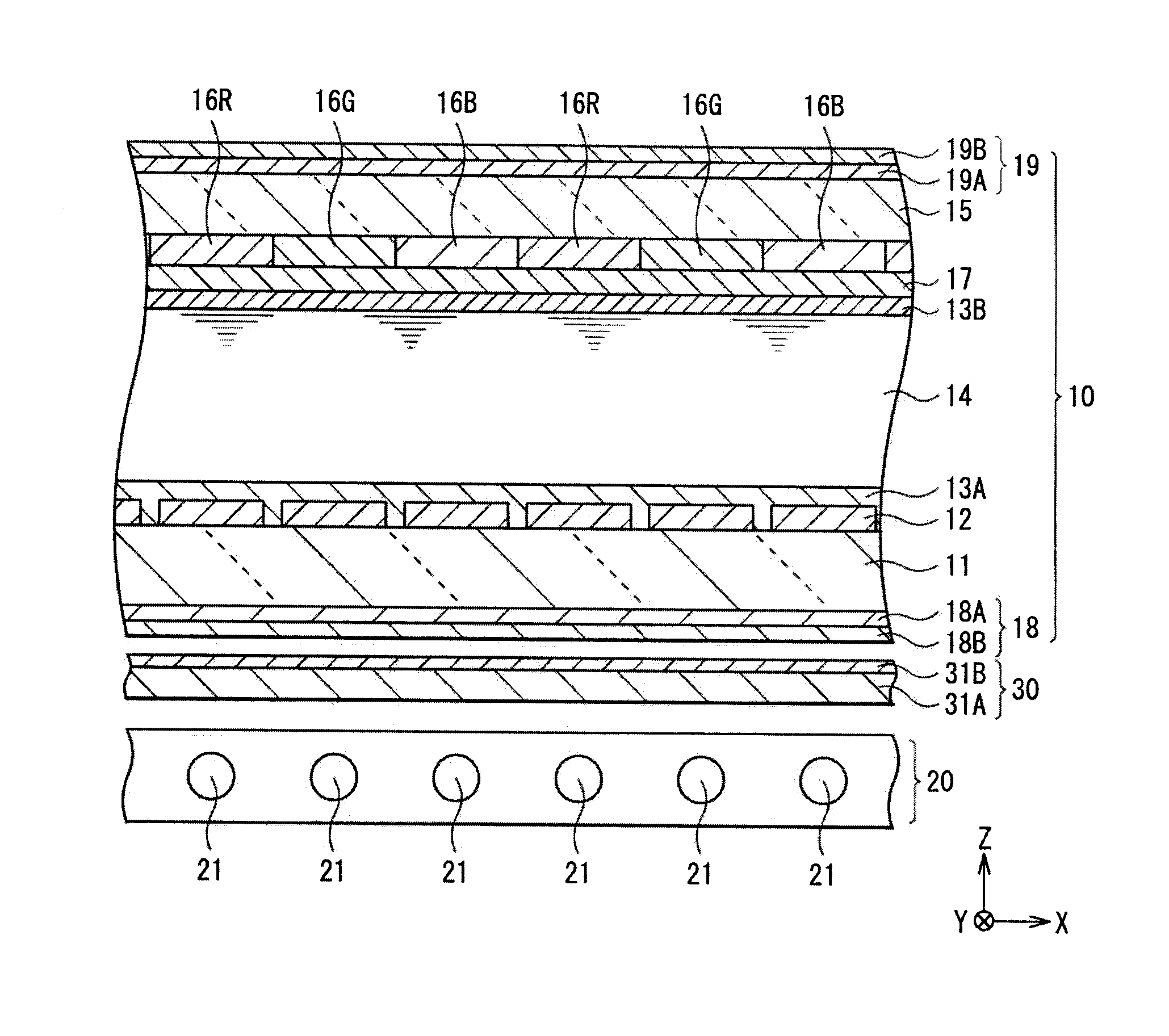
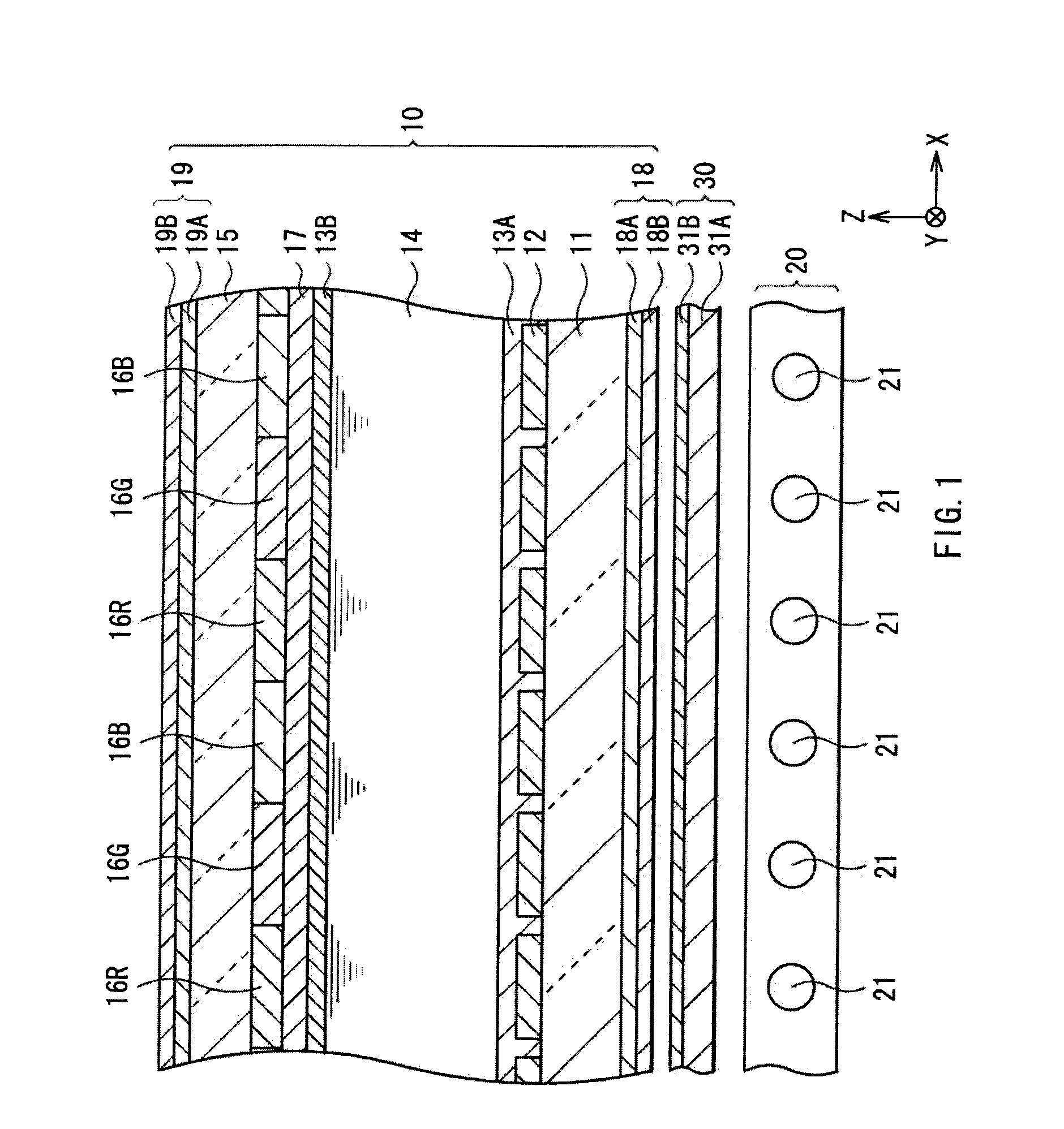
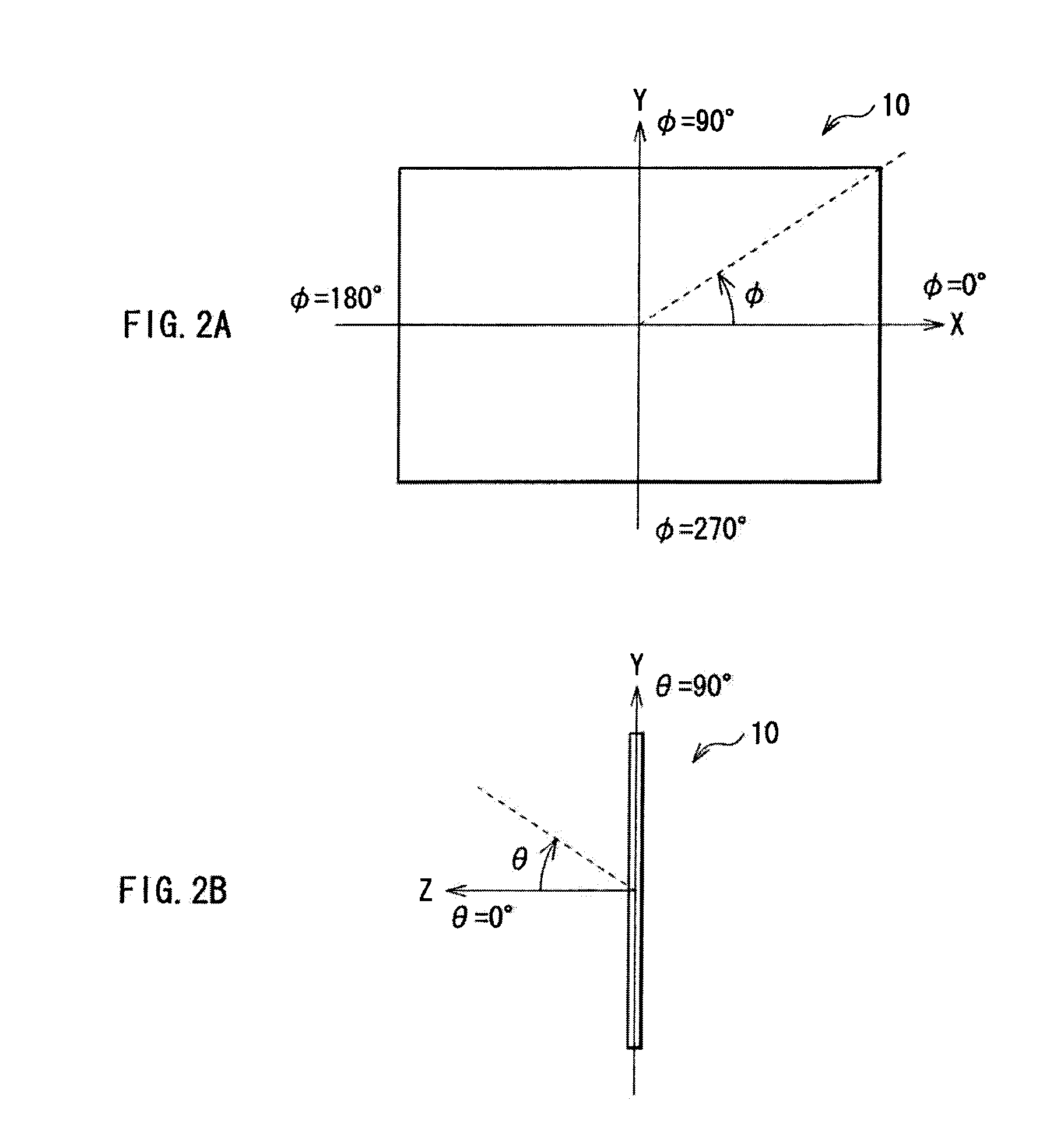
[0045]FIG. 1 schematically illustrates a sectional configuration of a liquid crystal display device according to a first embodiment of the invention, and FIGS. 2A and 2B illustrate an azimuth angle direction and a polar angle direction of the liquid crystal display device respectively. FIG. 3 illustrates spectra of leakage light in black display of a liquid crystal display panel illustrated in FIG. 1, FIG. 4 illustrates transmission spectra of a color correction filter illustrated in FIG. 1, and FIG. 5 illustrates a sectional configuration of part of the color correction filter illustrated in FIG. 1 in an enlarged manner. The liquid crystal display device has a liquid crystal display panel 10, a backlight unit 20, and a color correction filter 30 provided between the panel 10 and the backlight unit 20. The liquid crystal display device is, for example, an active-matrix d...

second embodiment

2. Second Embodiment

Example of Liquid Crystal Display Device Using Another Color Correction Filter

[0087]FIGS. 6A and 6B illustrate a color correction filter 40 mounted in a liquid crystal display device according to a second embodiment, where FIG. 6A illustrates a sectional configuration along a line VI(A)-VI(A) of FIG. 6B, and FIG. 6B illustrates a planar configuration as seen from a liquid crystal display panel 10 side.

[0088]The embodiment has the same configuration as that in the first embodiment except that the color correction filter 40 described later is used in place of the color correction filter 30 having the cholesteric liquid crystal polymer layer 31A and the quarter-wavelength layer 31B.

[0089]Color Correction Filter

[0090]The color correction filter 40 has a coloring layer 43 configured of a plurality of rectangular island portions (unit coloring layers 42) discretely provided on a surface on a liquid crystal display panel 10 side of a transparent base 41 having a pair of...

examples

[0118]Examples of the invention will be described in detail.

Experimental examples 1-1 to 1-48

[0119]First, simulation was made on a view angle characteristic in black display of the liquid crystal display panel 10 mounted in the liquid crystal display device illustrated in FIG. 1. In this case, LCD MASTER manufactured by SHINTEC, Inc. was used as simulation software.

[0120]In simulation, phase difference R0 in an in-plane direction and phase difference Rth in a thickness direction of the phase difference layers 18A and 19A of the polarizing plate 18 and 19, and phase difference Δnd at a wavelength 590 nm of the liquid crystal layer 14 including vertically-aligned liquid crystal were set as illustrated in Tables 1 and 2. In such setting, transmission axes of the polarizing plates 18 and 19 were assumed to be orthogonal to each other, and extend in a direction of an azimuth angle φ=0° (180°) and in a direction of an azimuth angle 90° (270°). Based on the setting, hues seen in vertical a...


PUM


Abstract

A liquid crystal display device, without light leakage in a black display mode, is provided. The liquid crystal display (LCD) device includes a LCD panel, a light source, and an optical filter between the LCD and the light source. When the LCD panel is in the black display mode without the optical filter, leakage light leaking from the LCD panel in an oblique direction shows a hue having a local minimum value in a wavelength range from 450 nm to 550 nm. Normal incident light entering into the LCD in a normal direction shows a hue same as that of light just emitted from the light source, and oblique incident light entering into the LCD panel in an oblique direction shows a hue having a local maximum value in a wavelength range from 400 nm to less than 550 nm.

Description

BACKGROUND OF THE INVENTION[0001]1. Field of the Invention[0002]The present invention relates to a liquid crystal display device modulating light for picture display.[0003]2. Description of Related Art[0004]Recently, a liquid crystal display device is mainly used as a display monitor of a television, a notebook computer, a car navigation device or the like. The liquid crystal display device is classified into various modes (types) depending on arrangement of liquid crystal molecules between panel substrates of the device. For example, a TN (Twisted Nematic) mode and an IPS (In-Plane Switching) mode are listed. In addition, an OCB (Optically Compensatory Bend) mode and a VA (Vertically Aligned) mode are listed. In particular, a VA-mode liquid crystal display device is now noticed because high contrast is easily achieved thereby.[0005]The VA-mode liquid crystal display device has a liquid crystal display panel 100 and a light source 101, for example, as illustrated in FIG. 23. The liq...

Claims


Application Information

Patent Timeline
IPC IPC(8): G02F1/1335
CPCG02B5/201G02F1/133609G02B5/223
Inventor MAEDA, TSUYOSHIOGASAWARA, TOYOKAZU
Owner SONY CORP
Learn More