Low hysteresis bearing

a bearing and low hysteresis technology, applied in the field of low hysteresis bearings, can solve the problems of unnecessary expense of micro-actuators in the head gimbal assembly, and achieve the effects of low hysteresis pivot, negligible residual hysteresis, and increased translation error

Inactive Publication Date: 2010-11-25
FIRST PRINCIPALS
View PDF6 Cites 3 Cited by
  • Summary
  • Abstract
  • Description
  • Claims
  • Application Information

AI Technical Summary

Benefits of technology

[0017]The present invention is directed to a low hysteresis pivot bearing suitable for a variety of applications. The relationship between torque and angular displacement is substantially linear, with negligible residual hysteresis. The present pivot bearing decouples stiffness from hysteresis, without increasing translation error. When used as a pivot bearing for a rotary actuator within disk drives, expensive micro-actuators on the head gimbal assembly are unnecessary.

Problems solved by technology

When used as a pivot bearing for a rotary actuator within disk drives, expensive micro-actuators on the head gimbal assembly are unnecessary.

Method used


Image

  • Low hysteresis bearing
  • Low hysteresis bearing
  • Low hysteresis bearing

Examples


Embodiment Construction

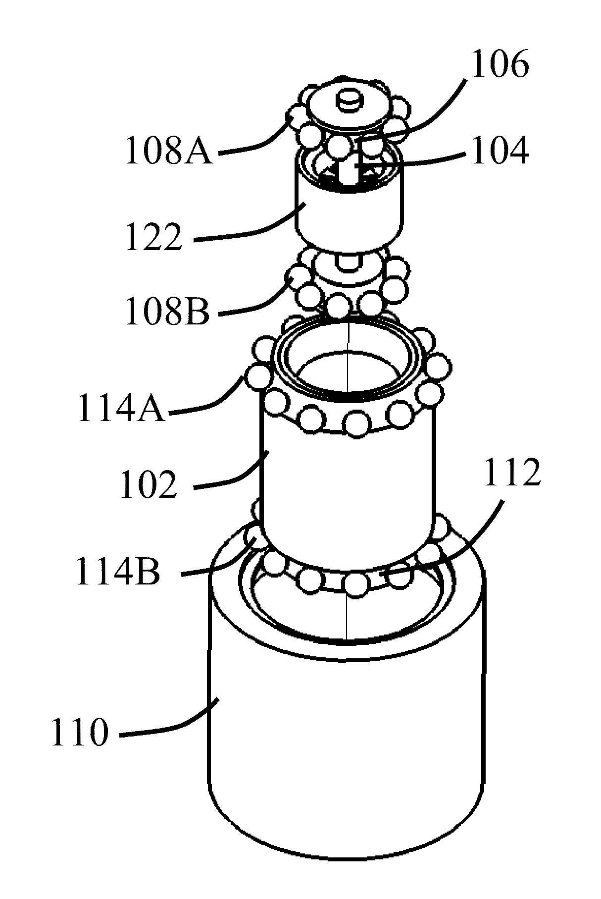
[0041]FIGS. 4 through 6 are various views of a pivot bearing 100 in accordance with an embodiment of the present invention. Inner sleeve 102 is rotatably supported on stationary shaft 104 by inner bearings 106. In the illustrated embodiment, the inner bearings 106 include upper bearing set 108A and lower bearing set 108B (collectively “108”). Consequently, the inner sleeve 102 is free to rotate concentrically around the stationary shaft 104. As will be discussed below, the inner bearings 106 can be subjected to a substantial pre-load without creating excessive hysteresis. In an alternate embodiment, the inner bearings 106 can be fixedly mounted to the inner sleeve 102.

[0042]Outer sleeve 110 is rotatably supported on inner sleeve 102 by outer bearings 112 (see FIG. 6). In the illustrated embodiment, the outer bearings 112 includes upper bearing set 114A and a lower bearing set 114B (collectively “114”). The outer bearings 112 are fixedly mounted to either the outer sleeve 110 or the ...


PUM

PropertyMeasurementUnit
rotationaaaaaaaaaa
torqueaaaaaaaaaa
position critical rotationaaaaaaaaaa

Abstract

A low hysteresis pivot bearing suitable for a variety of applications. The relationship between torque and angular displacement is substantially linear, with negligible residual hysteresis. The pivot bearing includes a pivot shaft and an inner sleeve pivotally attached to the pivot shaft by an inner bearing. An outer sleeve is pivotally attached to the inner sleeve by an outer bearing. An inner sleeve actuator continuously rotates the inner sleeve relative to the stationary shaft.

Description

CROSS-REFERENCE TO RELATED APPLICATIONS[0001]This application claims the benefit of the filing date of U.S. Provisional Patent Application Ser. No. 61 / 180,854 filed May 23, 2009, which is entitled “Low Hysteresis Bearing” which is hereby incorporated herein in its entirety by reference.FIELD OF THE INVENTION[0002]The present invention relates to a low hysteresis bearing suitable for a variety of applications, including as a pivot bearing for a rotary actuator within disk drives.BACKGROUND OF THE INVENTION[0003]Hard disk drives 30, such as illustrated in FIG. 1, employ rotary actuators 32 that position magnetic transducers 34 over selected information tracks on rotating magnetic disks 36. An example of a pivot bearing is disclosed in U.S. Pat. No. 6,631,053 (Chew). The transducers 34 are positioned with great accuracy by a closed-loop, servo system driven by voice coil motor (VCM) 38. The feedback in the control loop is provided by transducer 34 reading servo information pre-written ...

Claims


Application Information

Patent Timeline
Patent Type & Authority Applications(United States)
IPC IPC(8): G11B5/55F16C33/58
CPCF16C19/52F16C2370/12G11B5/5569F16C19/55
Inventor BOUTAGHOU, ZINE-EDDINE
Owner FIRST PRINCIPALS
Why Eureka
Try Eureka