Multi input timing recovery over packet network

a timing recovery and multi-input technology, applied in the field of packet network, can solve the problems of inability to accept many applications, and high level of jitter and wander of recovered reference clocks, so as to improve the estimate of delay, improve the reliability of packet impairment, and improve the effect of time-consuming

Active Publication Date: 2010-11-25
MICROSEMI SEMICON
View PDF15 Cites 26 Cited by
  • Summary
  • Abstract
  • Description
  • Claims
  • Application Information

AI Technical Summary

Benefits of technology

[0013]Embodiments of the present invention can provide a better estimate of the delay by exploiting multiple timing packet streams, and an inherent fault tolerance and robustness t

Problems solved by technology

One of the main challenges in this synchronization approach is that the timing packets are subjected to packet delay variations (PDV) inherent in any packet networks.
As a result, at the receiver side, depending on packet

Method used


Image

  • Multi input timing recovery over packet network
  • Multi input timing recovery over packet network
  • Multi input timing recovery over packet network

Examples


Embodiment Construction

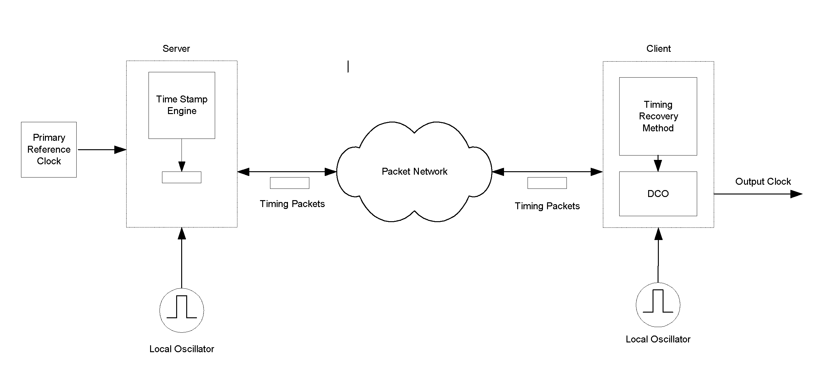
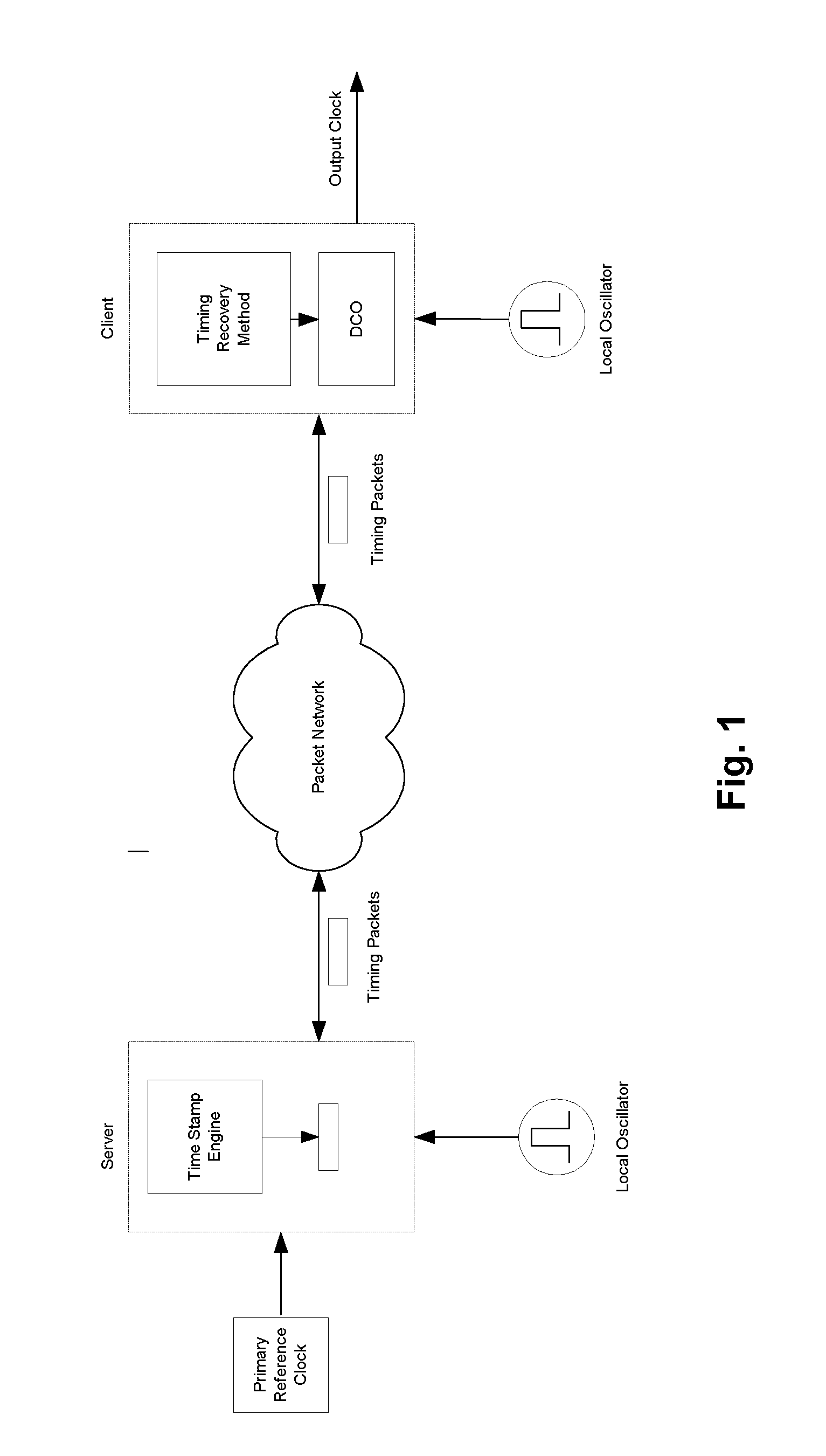
[0018]In the following description k is index to packet number, xj(k) represents transmitter time stamp for timing packet k, and timing packet stream j, yi(k) represents receiver time stamp for timing packet k and timing packet stream j, zi(k) is the raw delay estimate between transmitter and receiver for timing packet k and timing packet stream j, and ωi(k) is the filtered raw delay for timing packet k and timing packet stream j.

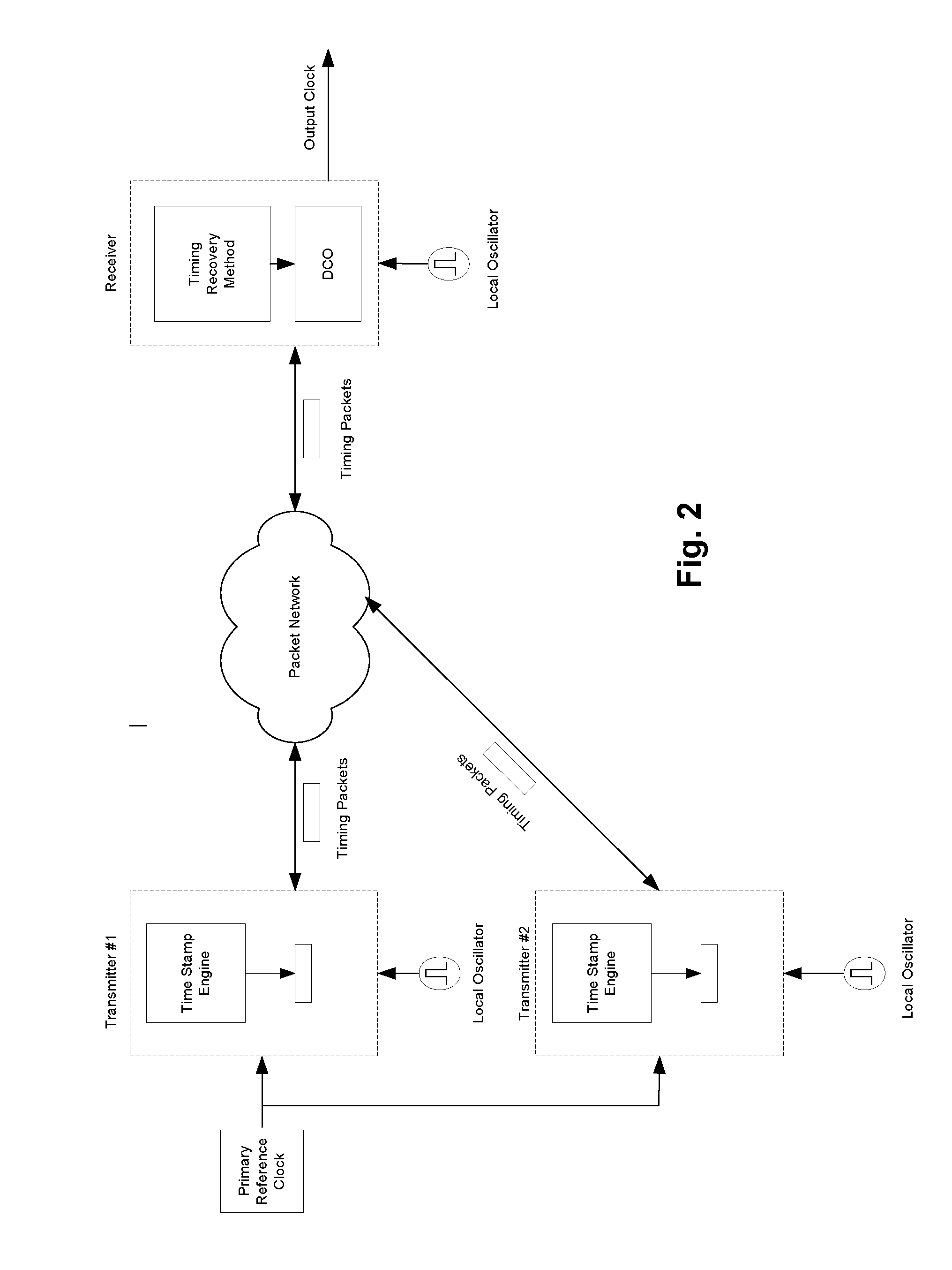
[0019]FIG. 3 is a block diagram of an embodiment of invention for the special case where there are only two timing packet streams from the same source and travelling over different paths, but it will be understood that the following description is applicable to the more general case of N timing packet streams.

[0020]For each stream j, raw delays (z(k)) are calculated by subtracting corresponding receiver local time stamps (yj(k)) generated by time stamp circuits 5000 from corresponding time-stamps generated by transmitter (xj(k)). The following can be writte...


PUM


Abstract

In a method of recovering timing information over packet networks, a receiver receives a plurality of packet streams over different paths from the same source. The raw delays experienced by the timing packets for each stream are filtered to provide a filtered delay for each stream. The filtered delays are weighted based on the quality of each stream, and the weighted filtered delays are then combined to form an aggregate delay estimate. Frequency adjustments for a local clock at the receiver are derived from the aggregate delay estimate.

Description

FIELD OF THE INVENTION [0001]This invention relates to packet networks, and in particular to a method of recovering timing information over such networks.BACKGROUND OF THE INVENTION[0002]In timing recovery over packet networks dedicated timing packets are time-stamped by the transmitter's clock and then are sent over a packet network (PSN) to one or multiple receivers. At the receiver side, these timing packets, as they arrive, are time-stamped by the receiver clock. The difference between these two time stamps represents the relative delay between transmitter and receiver clocks, which can be used to synchronize the two clocks. FIG. 1 is an illustration of this for the case where there is one transmitter and one receiver. One of the main challenges in this synchronization approach is that the timing packets are subjected to packet delay variations (PDV) inherent in any packet networks. As a result, at the receiver side, depending on packet delay variations, the recovered reference ...

Claims


Application Information

Patent Timeline
IPC IPC(8): H04J3/06
CPCH04J3/0661H04J3/0667H04J3/0682H04L43/0852H04J3/0644H04L7/0331H04L43/087H04L43/106H04L47/283H04J3/0679
Inventor RAHBAR, KAMRAN
Owner MICROSEMI SEMICON
Why Eureka
Try Eureka