Loading/unloading system serving a sheet cutting centre, feeding tray therefor and relative handling method

a technology of cutting centre and feeding tray, applied in the direction of metal-working feeding device, work trasfer device, metal-working auxiliary device, etc., can solve the problems of inability to impart an adequate force for lifting the weight of thick metal sheets, inability to operate the forklift correctly, and cost and performance time.

Active Publication Date: 2010-11-25
ASTES4 SA
View PDF6 Cites 9 Cited by
  • Summary
  • Abstract
  • Description
  • Claims
  • Application Information

AI Technical Summary

Benefits of technology

[0028]According to a further aspect, the suction-cup device comprises a housing head of ferro-magnetic material which supports one or more suction cups in fluid connection with a central fitting capable of arranging itself in correspondence of the central hole of the gripping head.
[0029]According to another asp...

Problems solved by technology

The main problem is due to the fact that the cut-in sheet cannot be fully disassembled into individual components, otherwise the forklift might not operate correctly.
Therefore, once the cut-in sheet has been unloaded, it is necessary to break these small connecting bridges to free the individual pieces from the off-cuts: this task is traditionally performed by hand, with the imaginable consequences in terms of cost and performance time.
Moreover, it is necessary that the suction loading system consists of a large number of small vacuum cups, otherwise it would be unable to impart an adequate force for lifting the weight of thick metal sheets.
As can be guessed, resorting to Cartesian mechanical hands makes the system more flexible, even though it causes more problems in terms of tuning.
In particular, the workpieces may be completely cut and separated from the cut-off structure, because they are then taken individually by the mechanical hands and orderly stacked in the unloading station, which makes useless the subsequent manual separation action.
As a matter of fact, in this field, as well as in similar fields, the handling system normally provides a single bridge crane whereon a single Cartesian mechanical hand is supported translatable, or a pair of mechanical hands, equipped with suction-cup ends: this configuration is not fully satisfactory ...

Method used


Image

  • Loading/unloading system serving a sheet cutting centre, feeding tray therefor and relative handling method
  • Loading/unloading system serving a sheet cutting centre, feeding tray therefor and relative handling method
  • Loading/unloading system serving a sheet cutting centre, feeding tray therefor and relative handling method

Examples


Embodiment Construction

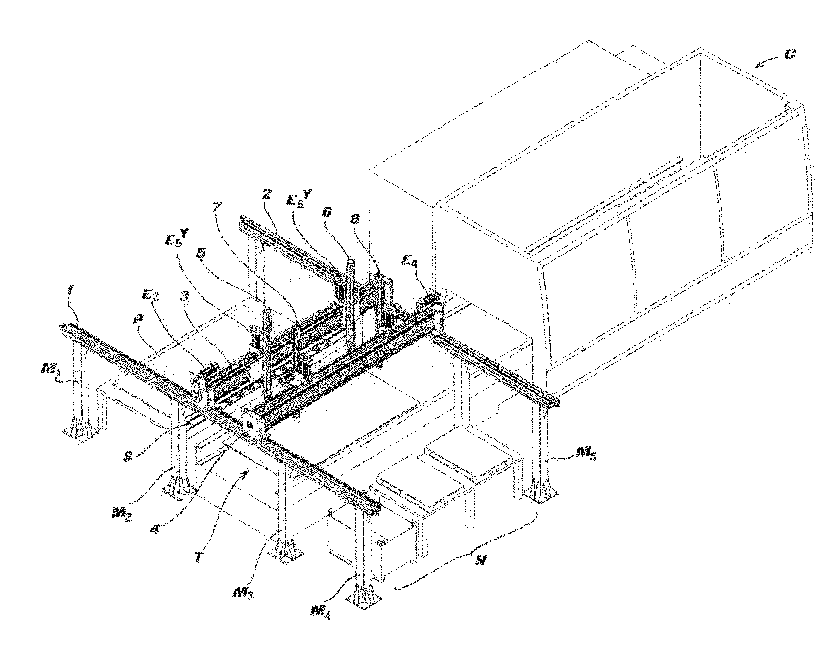
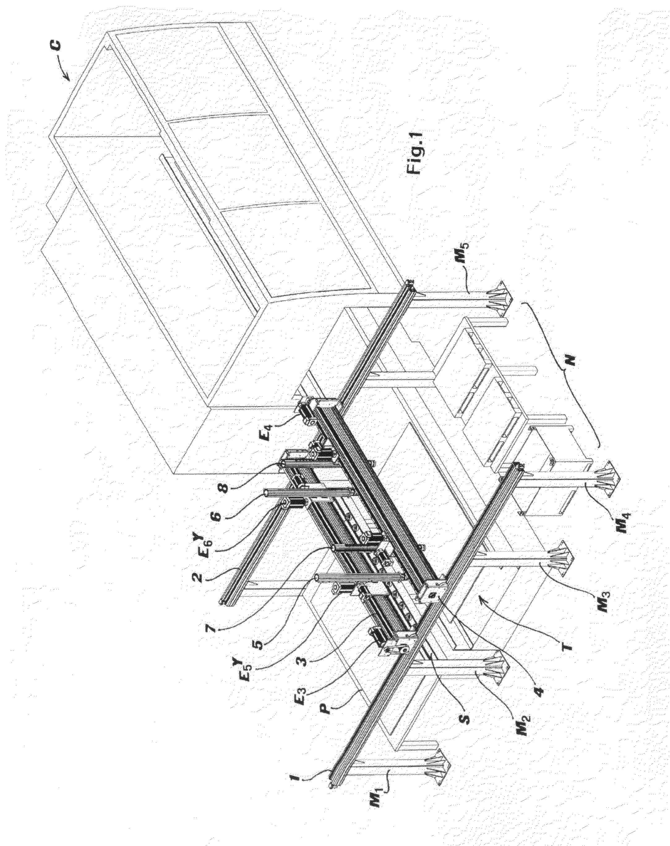
[0040]FIG. 1 schematically shows a cutting centre C provided with a conventional feeding tray T, whereon the virgin sheet and the cut-in sheet are supported for the introduction into and removal from cutting centre C.

[0041]Across feeding tray T, in a way conventional per se, two sliding rails 1 and 2 are provided, supported at the desired height by respective posts M1-Mn.

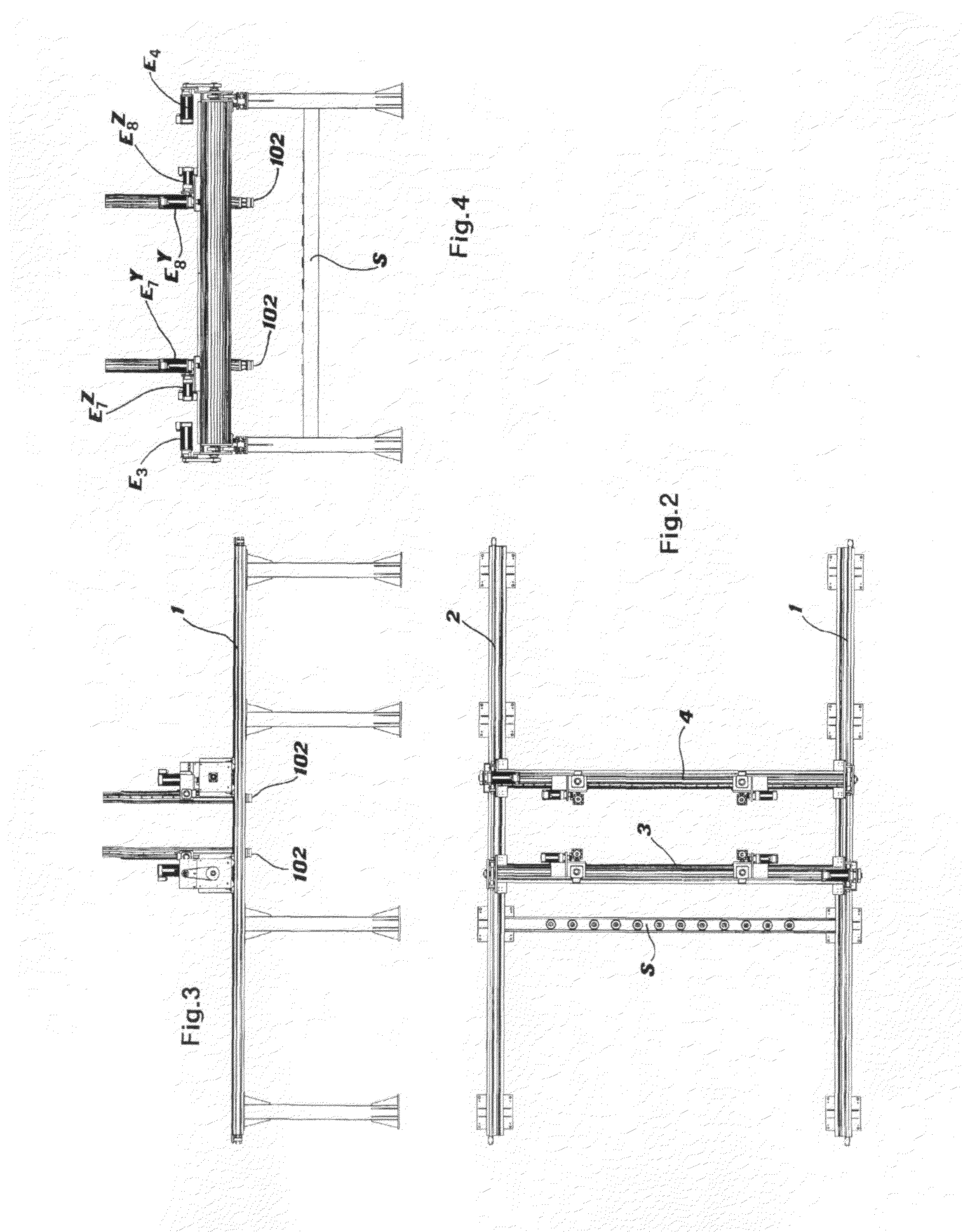
[0042]According to the invention, sliding rails 1 and 2 support a pair of sliding bridge cranes 3 and 4, each in turn being provided with a transversal sliding guide for a pair of robotized hands, 5, 6 and 7, 8, respectively.

[0043]For the movement on rails 1 and 2, each of bridge cranes 3 and 4 is provided, in a way known per se, with an electric handling motor (X axis), E3 and E4, respectively.

[0044]Each robotized hand 5-8 is configured so as to be able to translate on its own bridge crane, but also to translate vertically for lowering or raising a pick-up head arranged at the lower end.

[0045]For such purpose, elec...


PUM

PropertyMeasurementUnit
Thicknessaaaaaaaaaa

Abstract

A system for loading/unloading sheets is disclosed, some of which also being of metal, and handling method thereof, serving a laser cutting centre. The system includes a pair of rails (1, 2), supported at a preset height above a feeding tray (T) of the cutting centre, whereon at least one Cartesian robotized hand is movably mounted, capable of moving along horizontal axes X and Y as well as along a vertical axis Z, mutually orthogonal, and including at least two bridge cranes (3, 4) sliding along the rails (1, 2) each of which supports at least one pair of robotized hands (5-8), and the robotized hands (5-8) have an electromagnetic pick-up head which may be coupled with a suction-cup device (103). Feeding tray (T) consists of bars whereon small tesserae (204) of ceramic material are fitted.

Description

FIELD OF THE INVENTION[0001]The present invention concerns a loading / unloading system for a cutting centre, in particular a system of the type employing Cartesian mechanical hands.BACKGROUND[0002]As known, metal sheet and panel cutting centres are systems intended for cutting planar surfaces, having sometimes a very complex perimeter, starting from a typically rectangular sheet (for example measuring 1500×3000 mm with a thickness ranging from 0,5 to 20 mm). The cut is performed employing various techniques, also based on the composition of the sheet material: for example, there are machines employing laser cutting, oxygen lance cutting, water-jet cutting, plasma cutting and so forth.[0003]A particular sector is that of metal sheet cutting, which is typically performed employing laser devices.[0004]In this sector, in the loading and unloading phase to and from the cutting centre, there is the need to handle sheets of a non-negligible weight. Typically, sheets are stored in a warehous...

Claims


Application Information

Patent Timeline
IPC IPC(8): B23Q7/04
CPCB21D43/105B21D43/28B23K26/38B23K37/0408B23K2201/18Y10T483/16B65G47/92B21D43/11Y10T483/165Y10T483/1738B65G47/912B23K2101/18B23Q7/04B65G47/91
Inventor MOSSI, JAMES
Owner ASTES4 SA
Why Eureka
Try Eureka