
Method for manufacturing a side-folded type elevated floor and a system thereof

a manufacturing method and elevated floor technology, applied in the field of elevated floors, can solve the problems of uneconomical use of elevated floors made of aluminum alloy, not meeting the requirements of saving energy, and consumption of energy, and achieve the effects of less energy consumption, accurate dimensions, and simple manufacturing method of the present invention

Inactive Publication Date: 2010-12-02
UNITED INTEGRATED SERVICES
View PDF8 Cites 7 Cited by
  • Summary
  • Abstract
  • Description
  • Claims
  • Application Information

AI Technical Summary

Benefits of technology

[0006]The objective of the present invention is to provide a method for manufacturing a side-folded type elevated floor and a system thereof. Since the amount of energy necessary for manufacturing the elevated floor is not large, the usage of such an elevated floor becomes very economical and conforms to the requirements for saving energy in the industry.
[0009]The present invention has advantageous features as follows. Manufacturing a steel elevated floor by a press-forming process consumes less amount of energy than that in the conventional elevated floor of aluminum material, thereby conforms to the requirements for saving energy in the industry. Furthermore, in comparison with the method of the present invention, the procedure for manufacturing the conventional elevated floor of aluminum material has one more step (burr-removing) to produce accurate dimensions. Therefore, the manufacturing method of the present invention is simpler.

Problems solved by technology

During the aluminum-melting step, since high temperature and large amount of energy are necessary for melting aluminum ingots, energy is consumed greatly.
As a result, using the elevated floor made of aluminum alloy becomes uneconomical and does not conform to the requirements for saving energy in the industry.

Method used


Image

  • Method for manufacturing a side-folded type elevated floor and a system thereof
  • Method for manufacturing a side-folded type elevated floor and a system thereof
  • Method for manufacturing a side-folded type elevated floor and a system thereof

Examples


Embodiment Construction

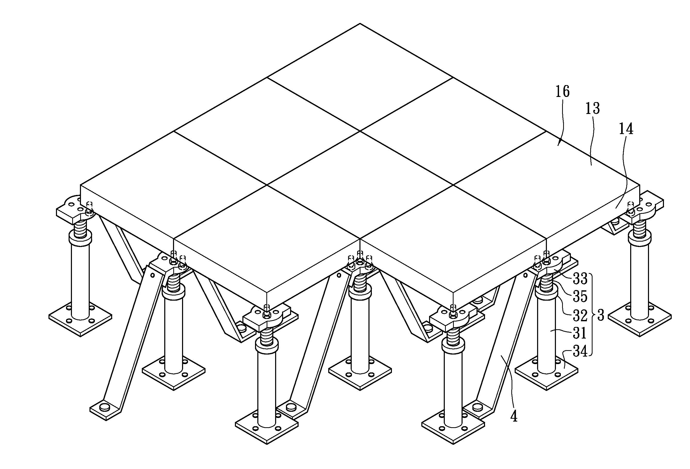
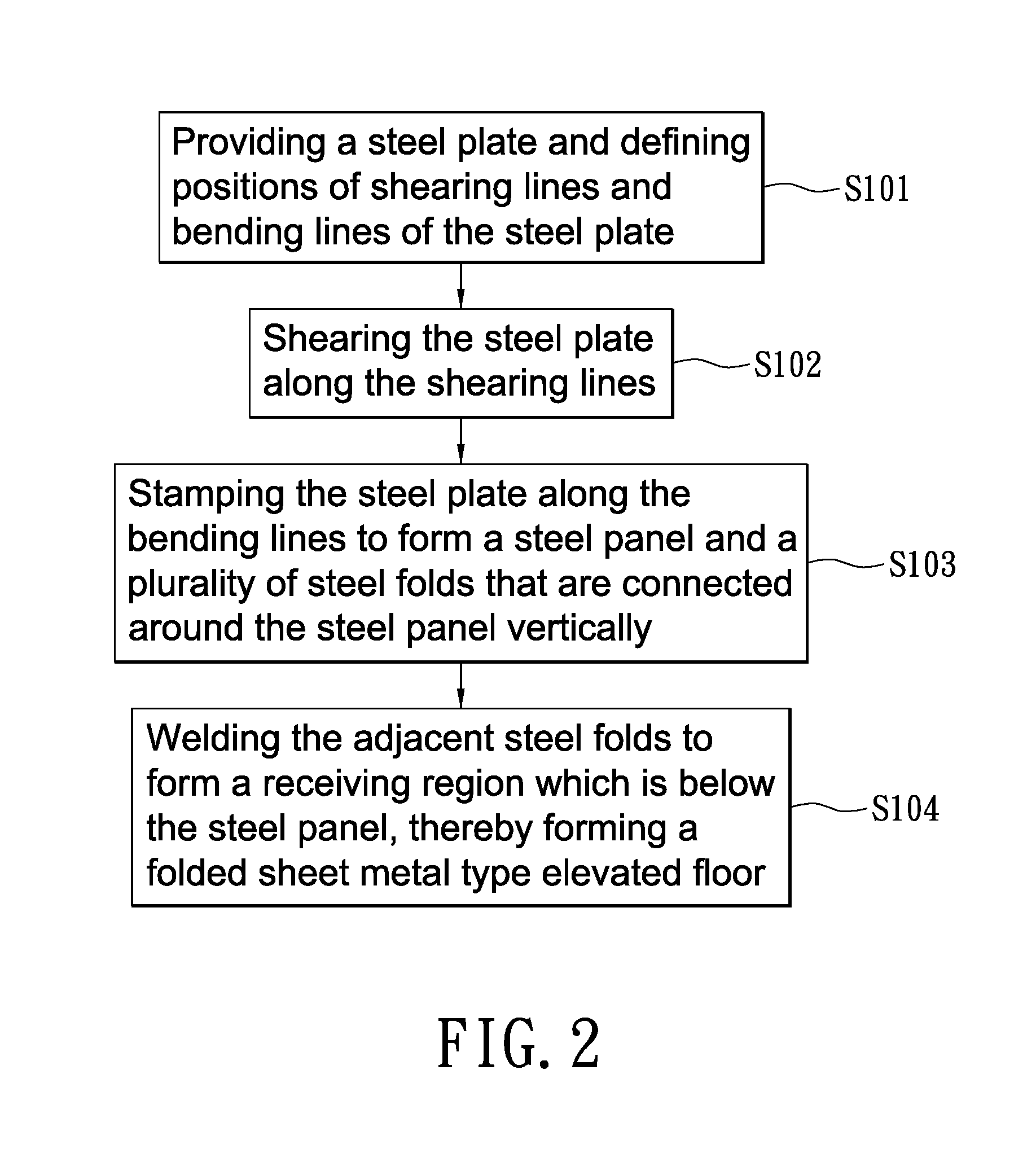
[0021]Please refer to FIGS. 2 to 5. The present invention is to provide a method for manufacturing a side-folded type elevated floor, which includes the steps of S101 to S104.

[0022]In the step S101, a square steel plate 1 is provided, and the positions of shearing lines 11 and bending lines 12 are defined (FIG. 3). In the present embodiment, there are four shearing lines 11 and four bending lines 12. Each of the bending lines 12 is separated from one side of the steel plate 1 by a distance respectively and these bending lines 12 are parallel to each other. One end of each shearing line 11 is connected to the intersection of the respective bending lines 12, while the other end is perpendicular to one side of the steel plate 1.

[0023]In the step S102, the steel plate 1 is sheared along the shearing lines 11.

[0024]In the step S103, the steel plate 1 is stamped along the bending lines 12, thereby forming a steel panel 13 and a plurality of steel folds 14 that are connected around the ste...


PUM

PropertyMeasurementUnit
temperatureaaaaaaaaaa
energyaaaaaaaaaa
dimensionsaaaaaaaaaa

Abstract

A method for manufacturing a side-folded type elevated floor includes the steps of: providing a steel plate and defining positions of shearing lines and bending lines of the steel plate; shearing the steel plate along the shearing lines; stamping the steel plate along the bending lines to form a steel panel with a plurality of steel folds that are bendingly connected around the steel panel; and welding the adjacent steel folds to form an accommodating region; thereby a side-folded type elevated floor is formed. In this way, the amount of energy consumed in manufacturing the elevated floor can be reduced greatly, thereby conforming to the requirement for saving energy. A side-folded type elevated floor system is further provided.

Description

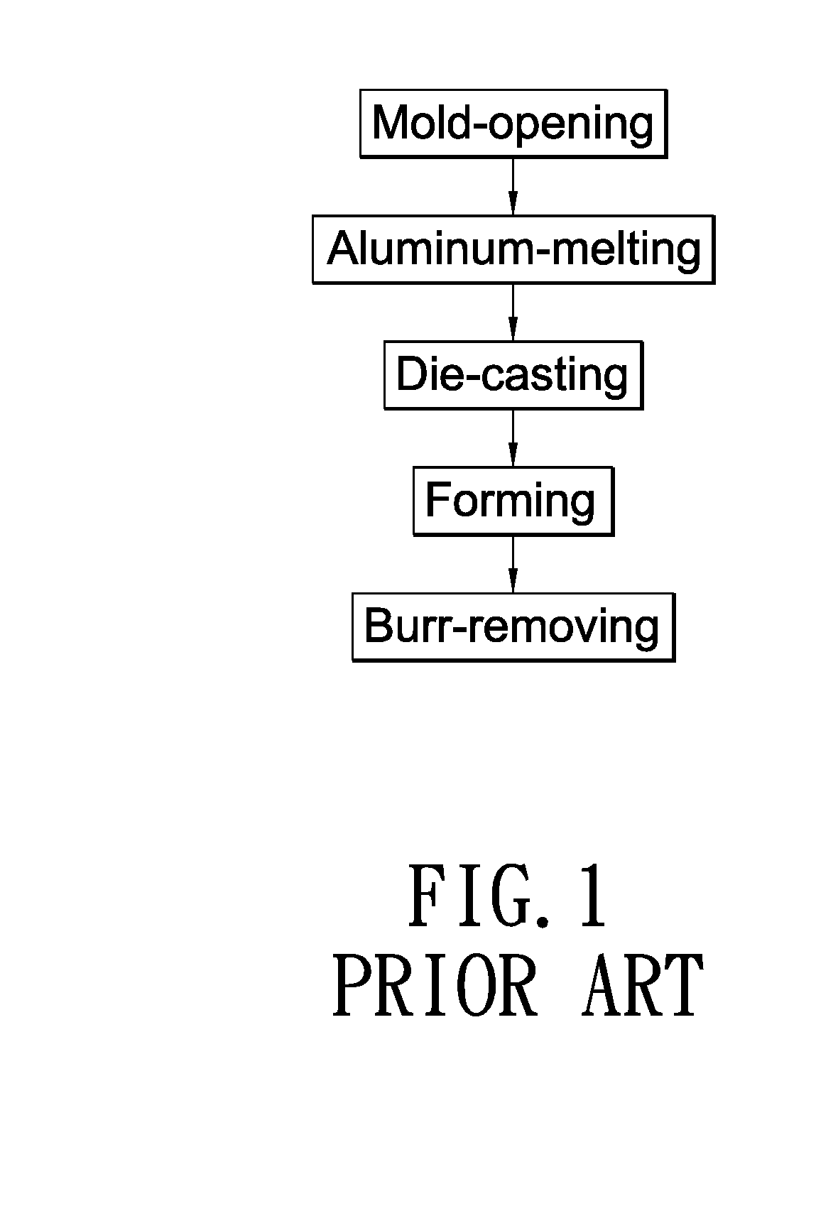
BACKGROUND OF THE INVENTION[0001]1. Field of the Invention[0002]The present invention relates to an elevated floor, in particular, to a side-folded type elevated floor.[0003]2. Description of Related Art[0004]Some factories and computer rooms may be provided with elevated floors to hide computers, electric lines, or connecting lines of electric appliances. Alternatively, an air-exhausting device is provided between the elevated floor and the ground to draw dust attached to the elevated floor. The currently available elevated floor in the market is manufactured by means of die-casting molten aluminum. As shown in FIG. 1, the die-casting process for aluminum alloy involves five steps including mold-opening, aluminum-melting, die-casting, forming, and burr-removing. During the aluminum-melting step, since high temperature and large amount of energy are necessary for melting aluminum ingots, energy is consumed greatly. As a result, using the elevated floor made of aluminum alloy becomes...

Claims


Application Information

Patent Timeline
Patent Type & Authority Applications(United States)
IPC IPC(8): E04F15/024
CPCB21D5/00B21D51/06E04F15/02447E04F15/02405B21D51/52
Inventor WANG, YEN-CHUNWANG, PONG-PING
Owner UNITED INTEGRATED SERVICES
Learn More