Exhaust gas combustion device and power generator including the same

Active Publication Date: 2010-12-02
YAMABIKO CORP
View PDF5 Cites 11 Cited by
  • Summary
  • Abstract
  • Description
  • Claims
  • Application Information

AI Technical Summary

Benefits of technology

[0025]Moreover, power from the power generating unit is supplied to the heater. Thus, even if the load connected to the power generating unit is a light load, it is possible to create a high-load state as a whole with the load thus connected and the heater as another load added altogether. This, as a result, increases the temperature of the exhaust gas discharged from the diesel engine to

Problems solved by technology

It is therefore difficult for such diesel engine to perform self regeneration of its filter by combusting fuel with exhaust gas.
First, clogging of a DPF may be prevented by performing maintenance, i.e., thermal regeneration on a regular basis before the DPF is clogged. In this case, however, the thermal regeneration requires use of a dedicated filter regeneration mechanism. Moreover, clogging may be cleared by heating with a heater included in the DPF, but such case requires an additional commercial power supply for electrifying the heater. Hence, these cases have a problem of limiting the operat

Method used


Image

  • Exhaust gas combustion device and power generator including the same
  • Exhaust gas combustion device and power generator including the same
  • Exhaust gas combustion device and power generator including the same

Examples


Example

Configurations of Exhaust Gas Combustion Device and Power Generator

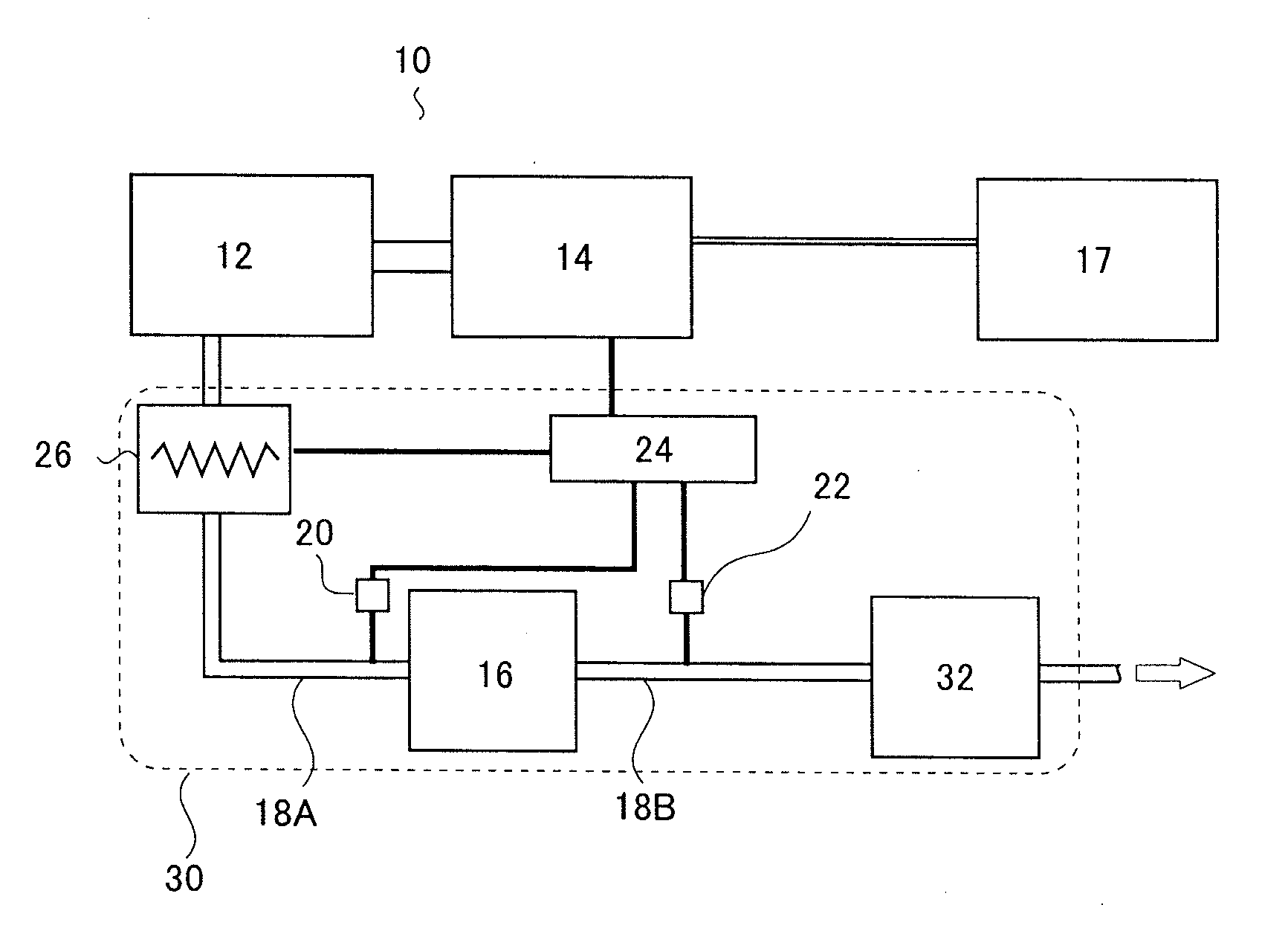
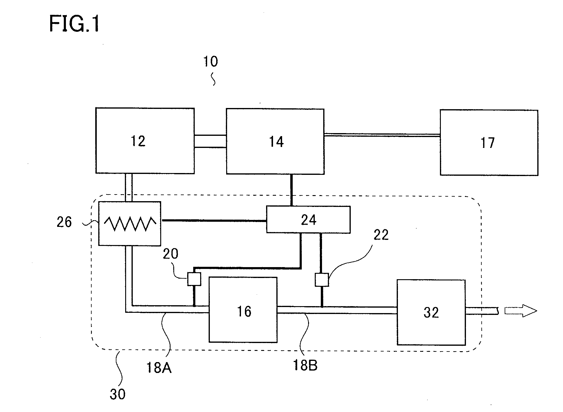
[0030]A power generator 10 including an exhaust gas combustion device 30 of an embodiment will be described with reference to FIG. 1. The power generator 10 shown in FIG. 1 actuates a load 17 by driving a power generating unit 14 by an engine 12. Exhaust gas discharged from the engine 12 is released to the outside after combusted by the exhaust gas combustion device 30.

[0031]The engine 12 is a diesel engine whose fuel (light oil, etc.) injection quantity is controlled mechanically by a mechanical governor, and has a function of driving (rotating) the power generating unit 14. Specifically, in the engine 12, fuel is compressed and injected by a mechanical injection pump, and the quantity of the injection by this injection pump is controlled by the mechanical governor.

[0032]The exhaust gas discharged from the engine 12 is purified by passing through an exhaust pipe 18A, a DPF 16, an exhaust pipe 18B, and a muffler 32 i...


PUM


Abstract

Provided is an exhaust gas combustion device which is capable of early prevention of clogging, and also a power generator including the device. An exhaust gas combustion device of the present invention includes: a DPF; a sensor which measures the pressure of exhaust gas to be introduced into the DPF; a sensor which measures the pressure of exhaust gas purified by the DPF; and a controller which receives outputs from both sensors and calculates a pressure difference. When the pressure difference is equal to or larger than a preset threshold, the heater is supplied with power from a power generating unit to thereby heat exhaust gas. Accordingly, PM accumulated inside the DPF is combusted and removed, preventing excessive clogging of the DPF even during light-load operation.

Description

BACKGROUND OF THE INVENTION[0001]1. Field of the Invention[0002]The present invention relates to an exhaust gas combustion device and a power generator including the device. In particular, the present invention relates to an exhaust gas combustion device that combusts exhaust gas discharged from a diesel engine and also to a power generator including the device.[0003]2. Description of the Related Art[0004]A general power generator obtains power by driving a power generating unit by an engine. When a diesel engine is employed as the engine, particulate matter (hereinbelow, abbreviated as PM) contained in exhaust gas from the engine needs to be removed.[0005]One method for removing PM from exhaust gas is to dispose a diesel particulate filter (hereinbelow, abbreviated as DPF) made of a porous material in an exhaust pipe through which exhaust gas discharged from a diesel engine passes. By this method, most of the PM contained in the exhaust gas is collected by the DPF. Therefore, the e...

Claims


Application Information

Patent Timeline
IPC IPC(8): F01N3/021F01N3/00
CPCF01N3/027F01N9/002Y02T10/47F01N2590/00F01N2900/0601F01N2560/08Y02T10/40
Inventor UEMOTO, TAMAKI
Owner YAMABIKO CORP
Why Eureka
Try Eureka