

Magnetocaloric generator
a generator and magnetocaloric technology, applied in the direction of energy-saving heating/cooling, machines using electric/magnetic effects, machine operation mode, etc., can solve the problems of reducing the overall energy efficiency of the generator, limiting the useful calorific output, etc., to improve the efficiency of the magnetocaloric generator, increase the economic profitability, and improve the calorific power
- Summary
- Abstract
- Description
- Claims
- Application Information
AI Technical Summary
Benefits of technology
Problems solved by technology
Method used
Image

Examples
first embodiment
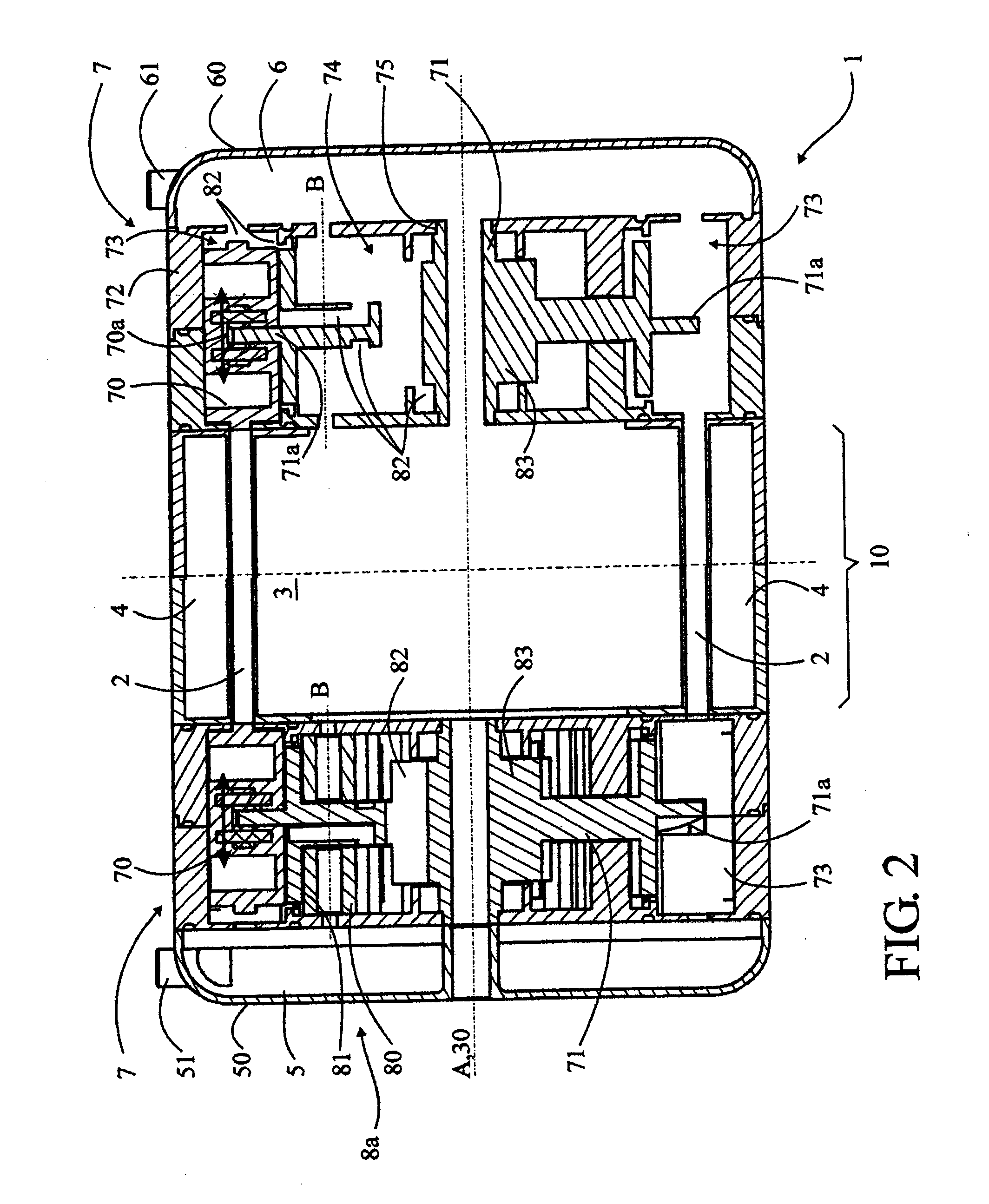
[0034]In the first embodiment illustrated in FIGS. 2 to 4, the means of forced circulation 8a comprise a set of small planet gears 80, arranged in circle around the central axis A, supported by the body 72 and free in rotation around axes B integral with the body 2. For clarity purposes, the right part of FIG. 2 is simplified and does not show the small gears 80, only one small gear 80 is illustrated in FIG. 3 and cam 71 is not illustrated in the detail of FIG. 4. These gears 80 mesh with a crown gear 81 integral with the cam 71 and rotated around the central axis A. The rotation of cam 71 rotates the crown gear 81, which in turn rotates the small gears 80 which operate like mini gear pumps, i.e. driving via their teeth the heat transfer fluid contained in the tank 74 towards the pistons 70 and the active elements 2, to drive the fluid into a loop circulation. For this purpose, the body 72 delimits a pump housing 84 for each small gear 80, and fluid passages 82 (cf. FIG. 4) in the f...
second embodiment
[0035]In the second embodiment illustrated in FIGS. 5 and 6, the means of forced circulation 8b comprise at least one planet gear 84, and in the example illustrated three planet gears 84, with this number not being restrictive, arranged around the central axis A, at equal distance or not, supported by the body 72 and free in rotation around axes C integral with the body 2. These gears 84 mesh with a drive gear 85 (represented by a reference line in FIG. 5) integral with the cam 71 and rotated around the central axis A. The rotation of cam 71 rotates the drive gear 85, which in turn rotates the planet gears 84 which operate like mini gear pumps, i.e. driving via their teeth the heat transfer fluid contained in the tank 74 towards the pistons 70 and the active elements 2 to drive the fluid into a loop circulation. For this purpose, these gears 84 are associated with a fixed pump housing 86 mounted in the body 72, which has channels 87 for the circulation of the fluid around each gear ...
third embodiment
[0036]In the third embodiment illustrated in FIGS. 7 to 9, the means of forced circulation 8c comprise a central piston 90 subjected to a reciprocating translation movement to operate like a piston pump and to create an alternate circulation of the fluid. This central piston 90 is mounted free in translation and in rotation on the drive shaft 30 of the magnetic arrangement 3. This drive shaft 30 supports a toothed wheel 91 that meshes with one or more gears 92, arranged in a circle around the central axis A, at equal distance or not, supported by the body 72 and free in rotation around axes D integral with the body 72. These gears 92 mesh with an inner crown gear 93 that rotates a cam 94 around the central axis A. The cam 94 has the same function as the cam 71 from the previous examples and comprises the same type of cam profile 71a moving inside the groove 70a of the pistons 70 to drive them into a reciprocating translation and push the heat transfer fluid in the active elements 2....
PUM
 Abstract
Description
Claims
Application Information