Waterproof joint section forming method and wire harness provided with waterproof joint section formed by the method

a technology of waterproof joint section and forming method, which is applied in the direction of cycle, cable termination, coupling device connection, etc., can solve the problems of increasing cost, time becoming even longer, and difficult to deal with design changes, so as to reduce the number of parts, reduce the time and effort of mounting operation, and reduce the effect of spa

Inactive Publication Date: 2010-12-02
SUMITOMO WIRING SYST LTD
View PDF12 Cites 16 Cited by
  • Summary
  • Abstract
  • Description
  • Claims
  • Application Information

AI Technical Summary

Benefits of technology

[0031]Further, the respective wires are unlikely to be displaced since being closely held in the through holes of the waterproof rubber lid. However, by fixing the wires to the tape winding tongue piece by taping, the wires can be fixed to the protection cap and the waterproof rubber lid even if a tensile force acts on the wire harness from the outside.
[0032]As described above, according to the present invention, a plurality of wires are respectively inserted through a plurality of through holes formed in one waterproof rubber lid and the outer circumferential surfaces of the insulating coatings of the respective wires and the inner circumferential surfaces of the through holes are held in close contact for sealing. Thus, it is possible to reduce th

Problems solved by technology

However, the joint connector of this type requires the housing 1a formed by molding, is difficult to miniaturize and, in addition, requires a part such as a terminal or a busbar, which increases cost and makes it difficult to deal with a design change.
Particularly, in order to infiltrate the sealant 8 into the cl

Method used


Image

  • Waterproof joint section forming method and wire harness provided with waterproof joint section formed by the method
  • Waterproof joint section forming method and wire harness provided with waterproof joint section formed by the method
  • Waterproof joint section forming method and wire harness provided with waterproof joint section formed by the method

Examples


first embodiment

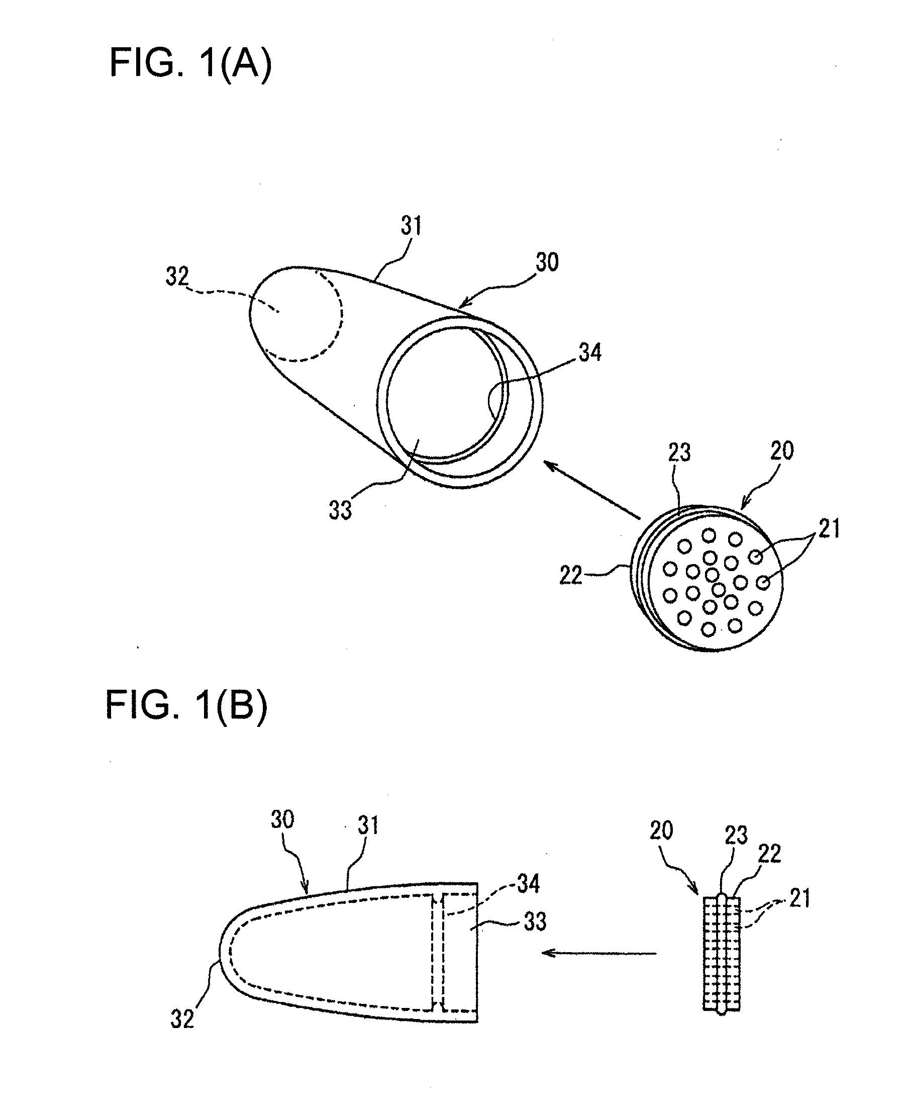
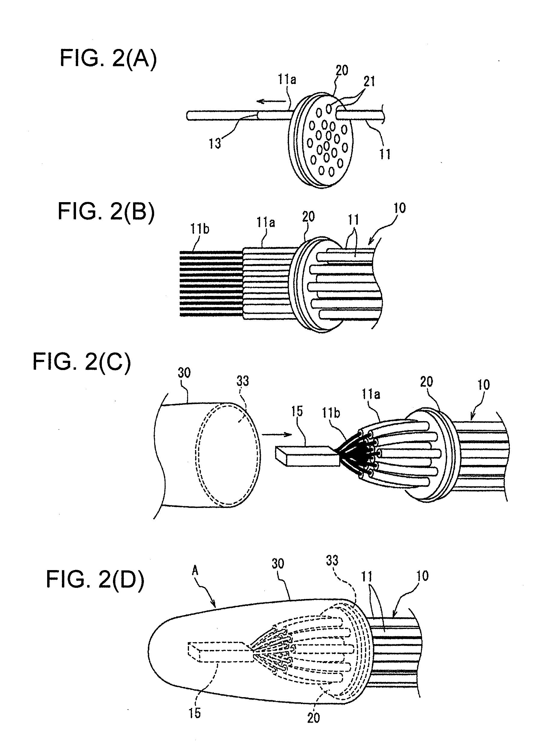
[0045]FIGS. 1 and 2 show a method for forming a waterproof joint section A according to the present invention and a wire harness provided with the waterproof joint section A.

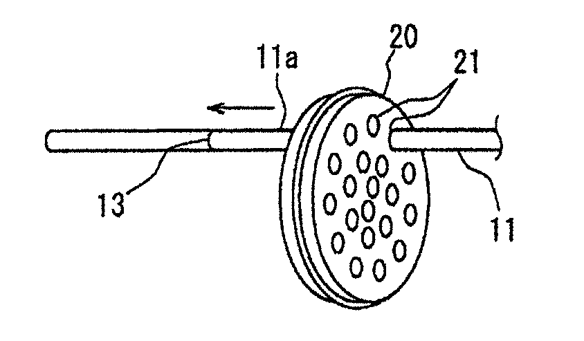
[0046]In a wire harness 10 to be arranged in an engine compartment of an automotive vehicle, a plurality of wires for a ground circuit (hereinafter, “ground wires”) 11 are electrically connected with each other by forming a joint section 15 at wire ends as shown in FIGS. 2(B) to 2(D) and a waterproof rubber lid 20 and a protection cap 30 shown in FIG. 1 are used to waterproof the joint section 15, whereby the waterproof joint section A is formed.

[0047]As shown in FIGS. 1(A) and 1(B), the waterproof rubber lid 20 has a disk shape with a right circular cross section and as many through holes 21 as the ground wires 11 to be joined are formed to penetrate the rubber lid 20 in a thickness direction. The inner diameters of the respective through holes 21 are so set that the through holes 21 are held in close contact w...

second embodiment

[0061]FIGS. 4 and 5 show the present invention.

[0062]In a wire harness 10-2 of the second embodiment, a terminal joint section is provided at a plurality of ground wires 11, a terminal joint section is also provided at a plurality of power wires 12, and these two terminal joint sections are accommodated in one protection cap.

[0063]Upon forming a waterproof joint section A of the wire harness 10-2, after the ground wires 11 and the power wires 12 are first respectively inserted through all through holes 21 of a waterproof rubber lid 20 as shown in FIG. 4, the passed-through leading end sides of the ground wires 11 and the power wires 12 are respectively grouped and cores 11b, 12b thereof are respectively exposed to form the terminal joint section 15 of the ground wires 11 and a terminal joint section 16 of the power wires 12.

[0064]A protection cap 30-1 for accommodating the separately formed terminal joint sections 15, 16 includes a partition wall 35 integral thereto and continuously...

third embodiment

[0067]FIGS. 6 and 7 show the present invention.

[0068]In the third embodiment, a wire harness 10-2 is taped and fixed to a tape winding tongue piece 38 projecting from a protection cap 30-2.

[0069]Specifically, as shown in FIG. 6, the tape winding tongue piece 38 projects in an arrangement direction of the wire harness 10-2 from an end surface of the peripheral wall of a tubular portion 31 of the protection cap 30-2 at an opening 33.

[0070]The wire harness 10-2 according to this embodiment is as follows. Similar to the second embodiment, after a terminal joint section 15 of ground wires 11 and a terminal joint section 16 of power wires 12 are separately accommodated into accommodating portions 36, 37 of the protection cap 30-2 and the opening 33 of the protection cap 30-2 is sealed by a waterproof rubber lid 20, the wires 11, 12 drawn out from the protection cap 30-2 are fixed to the tape winding tongue piece 38 by winding a tape 39.

[0071]Since the wires 11, 12 can be positioned and fi...


PUM


Abstract

Leading end sides of a plurality of wires to be electrically connected with each other are respectively inserted through a plurality of through holes formed in a waterproof rubber lid and the outer circumferential surfaces of insulating coatings of the respective wires are held in close contact with the inner circumferential surfaces of the respective through holes for sealing. The insulating coatings are peeled off at the passed-through ends of the wires to expose cores. The exposed cores are welded, fusion-bonded, soldered or fastened by a crimping terminal to form a terminal joint section. The terminal joint section is inserted into a protection cap made of a bottomed resin molding through an opening end. The waterproof rubber lid is fitted to an opening end of the protection cap to seal the interior of the protection cap accommodating the terminal joint section without injecting a waterproofing agent into the protection cap.

Description

BACKGROUND OF THE INVENTION[0001]1. Field of the Invention[0002]The present invention relates to a method for forming a waterproof joint section of a wire harness to be arranged in an automotive vehicle or the like and a wire harness including a waterproof joint section formed by such a method and is particularly designed to treat joined sections at ends of a plurality of wires without using a waterproofing agent.[0003]2. Description of the Related Art[0004]As a method for joining and connecting a plurality of wires constituting a wire harness at their ends, there are a method using a joint connector and a method for forming a terminal joint section by joining exposed core sections at the ends of the wires by welding, fusing or another means. In either case, this joint section needs to be waterproofed in the case of being arranged in a water susceptible area such as an engine compartment.[0005]FIG. 10 shows an example of connection using a joint connector disclosed in Japanese Unexa...

Claims


Application Information

Patent Timeline
IPC IPC(8): H02G15/02H01R43/00
CPCH01R4/22H01R13/5208H01R43/0207H01R43/28Y10T29/49194B60L11/1818B60L2200/12Y02T10/7005Y02T90/14H01R2201/26B60L53/16Y02T10/7072
Inventor MATSUOKA, KATSUSHISAWAMURA, NAOHITO
Owner SUMITOMO WIRING SYST LTD
Why Eureka
Try Eureka