Reducing drag on the web of a positive displacement sorter

a technology of positive displacement and web, which is applied in the direction of conveyor parts, packaging, transportation and packaging, etc., can solve the problems of increasing the drag of the sorter, increasing the electrical current or amp, and the web of the sorter experiencing an increase in drag, so as to reduce the drag

Active Publication Date: 2010-12-02
DEMATIC
View PDF17 Cites 3 Cited by
  • Summary
  • Abstract
  • Description
  • Claims
  • Application Information

AI Technical Summary

Benefits of technology

[0005]The present invention provides a method for reducing drag on the web of a positive displacement sorter that both positively identifies the cause and produces a satisfactory solution.

Problems solved by technology

From time to time, a sorter experiences an increase in drag on the web.
Such drag may result in an increase in the electrical current, or amps, drawn by the electric motor driving the web.
While an increase in electrical current is an indication that the web is experiencing an increase in drag, or mechanical resistance, it has proven illusive to determine the cause of the increased drag much less to provide a suitable solution that reduces drag and, hence, motor electrical current.
An increase in drag may express itself in other ways, such as an increase in audible noise as well as visual appearance of the web itself.
Such solution not only may fail to resolve the problem, it may also result in oil discharge to the floor, or the like.

Method used


Image

  • Reducing drag on the web of a positive displacement sorter
  • Reducing drag on the web of a positive displacement sorter
  • Reducing drag on the web of a positive displacement sorter

Examples


Embodiment Construction

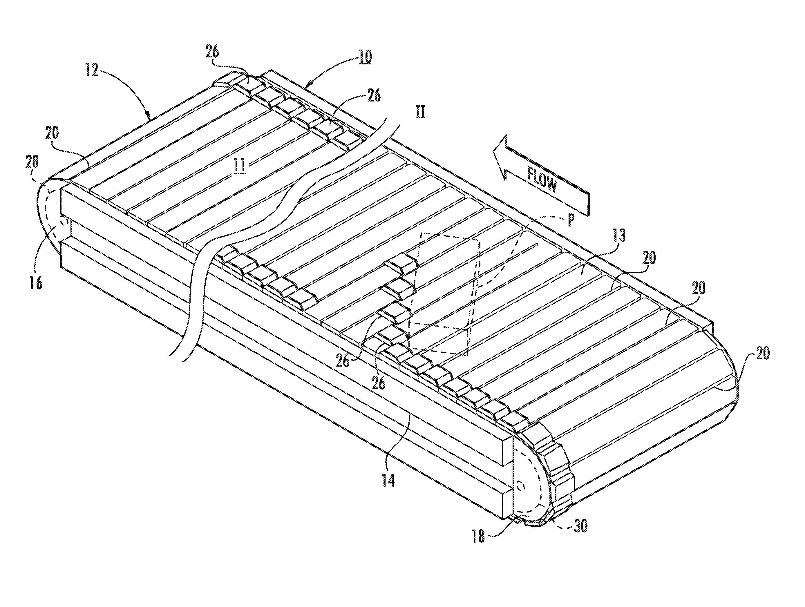
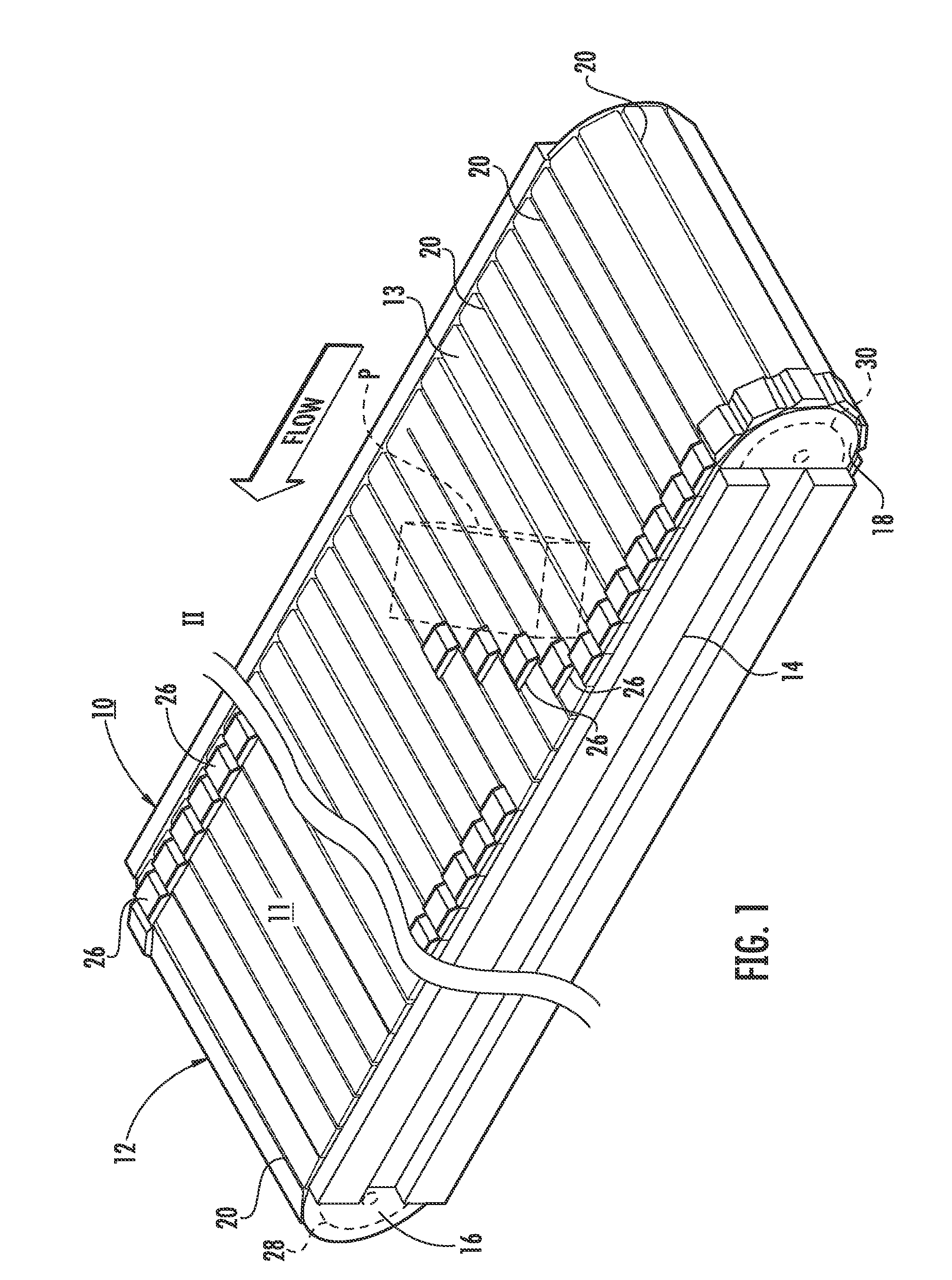
[0026]Referring to the drawings and the illustrative embodiments depicted therein, a positive displacement sorter 10 includes a moving web 12, an upper run of which defines a conveying surface 11 (FIG. 1). Web 12 is made up of a plurality of parallel slats 20 interconnected at their opposite ends with chain assemblies 22a, 22b (not shown in FIG. 1) in an endless loop and a plurality of pusher shoes 26, each traveling along at least one of slats 20. Sorter 10 further includes a driven sprocket assembly 28 at an article discharge end portion 16 of the conveying surface and a non-driven sprocket assembly 30 at an article charge end portion 18 of the conveying surface. As will be described in more detail below, each of sprocket assemblies 28, 30 include at least two sprockets on a shaft each for engaging one of chain assemblies 22a, 22b. Sprocket assemblies 28, 30 support chain assemblies 22a, 22b at opposite longitudinal ends of web 12. Details of sorter 10 are disclosed in commonly as...


PUM

PropertyMeasurementUnit
widthaaaaaaaaaa
frictionaaaaaaaaaa
positive displacementaaaaaaaaaa

Abstract

A method of reducing drag on the web of a positive displacement sorter is used with a web made up of a plurality of parallel slats interconnected at their opposite ends with chain assemblies in an endless loop. A plurality of pusher shoes each travel along at least one of said slats. The sorter further includes a driven sprocket assembly and a non-driven sprocket assembly. Each of the sprocket assemblies includes at least two sprockets on a shaft, each for engaging one of the chain assemblies. The sprocket assemblies support the chain assemblies at opposite ends of the web. The method includes auditing the sorter including determining if the slats are skewed with respect to the direction of travel of the web. If it is determined that the slats are skewed, then the chain assemblies and the non-driven sprocket assembly are modified. The chain assemblies are modified by adding side thrust wheels on opposite sides of the web. The non-driven sprocket is modified by locking the sprockets to the shaft such that the sprockets rotate together.

Description

CROSS REFERENCE TO RELATED APPLICATION[0001]This application claims priority from U.S. provisional patent application Ser. No. 61 / 181,138, filed on May 26, 2009, the disclosure of which is hereby incorporated herein by reference in its entirety.BACKGROUND OF THE INVENTION[0002]The present invention is directed to reducing drag on the web of a positive displacement sorter. While the invention may be used with a sorter that has been in use for some time and may have experienced degraded performance, it can also be installed with a new sorter as a preventative accessory.[0003]A positive displacement sorter includes a web that is made up of a plurality of parallel slats interconnected at their opposite ends with chains in an endless loop, the upper run of which defines a conveying surface. The endless loop, or conveyor, is driven by an electric motor. A plurality of pusher shoes travel along the slats in order to laterally displace articles carried by the conveying surface, such as to o...

Claims


Application Information

Patent Timeline
Patent Type & Authority Applications(United States)
IPC IPC(8): B65G19/22B65G47/46B23P6/00
CPCB65G17/06Y10T29/49718B65G2207/36B65G47/844
Inventor SCHUITEMA, DENNIS J.WOLF, STEPHEN C.KOOISTRA, KENNETH J.BERGHORN, DAVID M.
Owner DEMATIC
Why Eureka
Try Eureka