Shorten Temperature Recovery Time of Low Temperature Ion Implantation

Inactive Publication Date: 2010-12-02
ADVANCED ION BEAM TECHNOLOGY INC
6 Cites 14 Cited by

AI-Extracted Technical Summary

Problems solved by technology

However, a serious disadvantage of “condensed moisture” occurs when the temperature of the low temperature ion implantation is lower than room temperature.
Typically, this low temperature is below the freeze point of water, such as about −15˜−25° C. or even lower, while the temperature of the external environment usually is room temperature, such as about 15˜25° C. Therefore, if implanted and cooled wafers are directly moved from the chamber to the external environment immediately after the implanting process, the occurrence of “condensed moisture” on the surfaces of the wafers induced by the temperature difference almost is unavoidable.
Then, unpredictable damage on micro-structures of the wafers and/or side effects for following semiconducto...

Benefits of technology

[0010]The present invention provides a new approach for improving/correcting the condensed moisture problem by actively and ...

Abstract

The present invention discloses a low temperature ion implantation by performing a heating process after the end of an implanting process and before the wafer is moved into the external environment. This invention actively raises wafer temperature at a time no later than implementation of the vacuum venting process, such that the condensed moisture induced by the temperature difference between a vacuum environment inside ion implanter and an external environment outside ion implanter is effectively minimized. The wafer can be heated at a loadlock, a robot for transferring wafer and/or an implantation chamber. The wafer can be heated by a gas, a liquid, a light and/or a heater embedded in a holder for holding the wafer.

Application Domain

Electric discharge tubesSemiconductor/solid-state device manufacturing +1

Technology Topic

EngineeringMoisture +3

Image

  • Shorten Temperature Recovery Time of Low Temperature Ion Implantation
  • Shorten Temperature Recovery Time of Low Temperature Ion Implantation
  • Shorten Temperature Recovery Time of Low Temperature Ion Implantation

Examples

  • Experimental program(1)

Example

[0017]A detailed description of the present invention will be discussed in the following embodiments, which are not intended to limit the scope of the present invention and which can be adapted for other applications. While drawings are illustrated in detail, it is appreciated that the quantity of the disclosed components may be greater or less than that disclosed, except for instances expressly restricting the amount of the components.
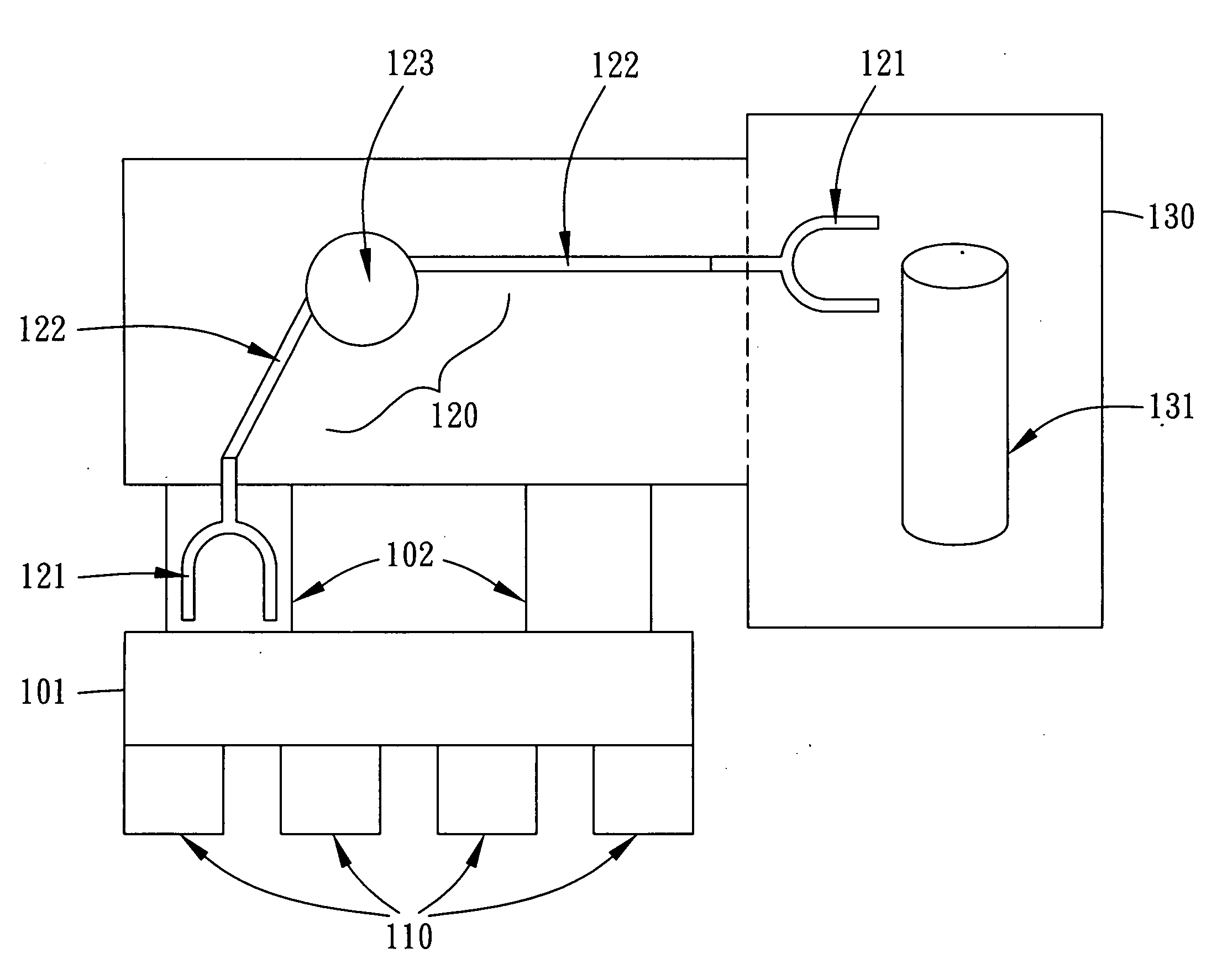
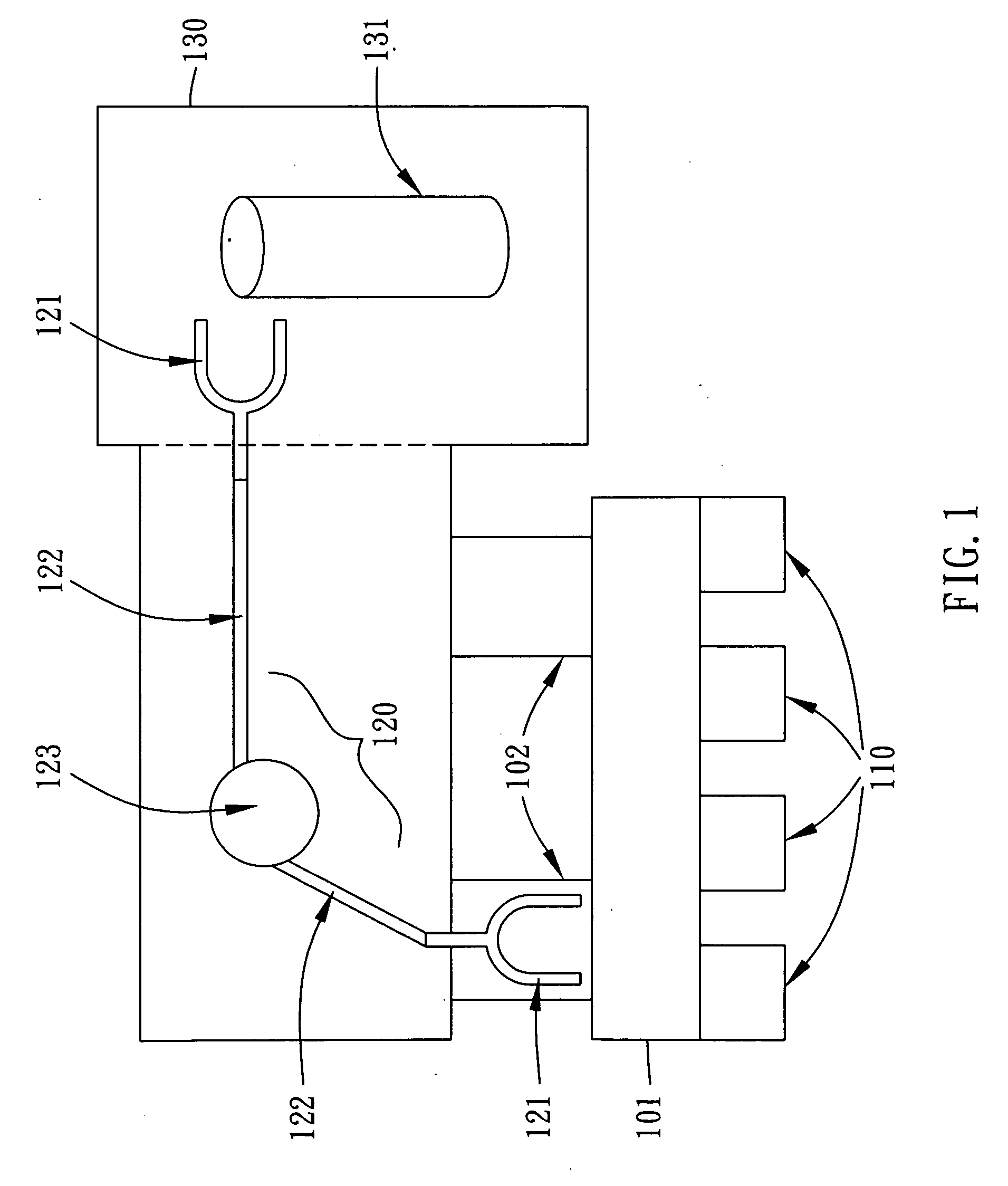
[0018]An ion implanter capable of performing low temperature ion implantation for use with the invention is briefly described below and illustrated in FIG. 1. The ion implanter comprises a robot transfer 101, a loadlock 102, a robot 120 and an implantation chamber 130. Many or most of the components may correspond to known elements. Herein, as usual, the robot transfer 101 is used as an interface between the ion implanter and the external environment, which always is in an atmospheric/ambient environment. Also, as usual, the loadlock 102 is used as an interface between a vacuum environment inside of the ion implanter and the robot transfer 101 (or the atmospheric environment), and can be in an atmospheric environment or a vacuum environment. The robot 120 is used to transfer wafers between the loadlock 102 and the implantation chamber 130, which can be located at the loadlock 102, the implantation chamber 130, or an independent robot chamber as shown in FIG. 1, and so on. Indeed, sometimes, there is another robot at the robot transfer 101, but it is omitted to simplify the figures herein. To perform an implanting process in a required low temperature, the implantation chamber 130 usually has a chuck for holding the wafer, a cooling mechanism for cooling the wafer, a motion mechanism for moving wafers to produce a relative motion between the wafer and ion beam, and so on. Herein, owing to these items not being directly related to how the wafer is heated after the wafer is implanted, the details on them are omitted with only a support mechanism 131 being illustrated to indicate the existence of all devices for implanting in a required low temperature context. The ion beam assembly for generating ion beams also is omitted from the figure, because it is not related to how the wafer is heated after the wafer is implanted.
[0019]Clearly, to be an interface between the external environment and vacuum environment, the loadlock 102 must allow for a vacuum venting process. In short, as usual, when a wafer is moved from the implantation chamber 130 into the loadlock 102, the loadlock 102 must also be in a vacuum environment. Then, to properly move the wafer into the external environment, the loadlock 102 must be changed to an environment equivalent to the external environment. Hence, a vacuum venting process must be performed to change the environment inside of the loadlock 102. In general, a hot-dry nitrogen gas is applied into the loadlock 102 to raise the pressure inside. Then, a door between the loadlock 102 and the robot transfer 101 is opened after the pressure inside of the loadlock 102 is equal to the pressure inside of the robot transfer 101. Finally, the wafer is moved from the robot interface 101 to the cassette 110 in a process having no simultaneous physical interaction with the operation of the implantation chamber 130.
[0020]As is commonly observed, condensed moisture appears on the wafer during and/or just after the vacuum venting process, because the pressure and the temperature of the gas around the wafer are significantly raised when the temperature of the wafer is still almost as low as the temperature of the implanting process.
[0021]One embodiment of this invention is based on improving the conventional vacuum venting process at the loadlock 102. The embodiment emphasizes that the wafer surface is closely contacted with the gas during the vacuum venting process. Therefore, the embodiment directly raises the temperature of the gas used for vacuum venting, and optionally increases the flow rate of the gas. Clearly, when the temperature of the gas is high enough, or when the heat carried by the gas is large enough, the wafer temperature can be rapidly increased in a short period. In other words, by adjusting the gas temperature and/or the gas flow rate, the embodiment can rapidly increase the wafer temperature before the wafer is moved into the cassette 110 (or the external environment). Therefore, when the temperature difference between the wafer and the external environment is decreased or even eliminated in a short period, not only is the condensed moisture problem improved or even prevented, but also the throughput is enhanced.
[0022]Of course, an ion implanter may have more than one loadlock. In such a situation, to save cost and simplify the construction of the ion implanter, it is possible for only partial ones of the loadlocks 102 to have the heat function with proper isolation value to isolate with other portions of the ion implanter. In such situations, only heat-function enabled loadlocks 102 are used to heat the wafer at a point no later than the time when the when the wafer is moved out of a vacuum environment. For example, an implementation can comprise only the loadlocks that move the wafer out of the vacuum environment being capable of and used to heat the wafer, with other ones of the loadlocks that only move the wafer into the vacuum environment not being capable of and used to heat the wafer.
[0023]An assembly of hardware for implementing the described embodiment is abbreviated in FIG. 2A. In a chamber 140, such as the chamber of the loadlock 102, a wafer 141 is held by a holder 142 for provision of gas 144 from a gas assembly 143 at a required temperature and/or flow rate. Herein, the gas 144 usually is N2, especially hot-dry N2, but also can be inset gas, gas without vapor or any gas which will not react with the wafer 141. Clearly, when the chamber 140 is filled with the gas 144, the wafer is surrounded (e.g., totally surrounded) by the gas 144 with the temperature of the wafer being commensurately raised. After that, when the wafer is moved out of the chamber 140, the condensed moisture problem is improved, or even prevented.
[0024]Significantly, the key is heating the wafer in the chamber 140 before the wafer is moved out, rather than how the wafer is heated within the chamber 140. The previous embodiment can be achieved, for example, by simply modifying conventional hardware already being used for vacuum venting. However, the invention can be achieved by other approaches, as well.
[0025]According to another embodiment of the invention, as shown in FIG. 2B, a liquid assembly 145 is used to provide a liquid 146 for heating the wafer. Again, by properly adjusting the temperature, and/or even the flow rate, of the liquid 146, the temperature of the wafer 141 can be suitably (e.g., properly) raised. However, to avoid any reaction between the wafer 141 and the liquid 146 (e.g., liquids at room temperature may react with the wafer and/or comprise water), it may be better for the liquid 146 only to contact the holder 142 and not (e.g., not directly contact) the wafer 141. For example, the liquid 146 can be located only inside of the holder 142 or can flood only the holder 142, such that the liquid 146 directly heats the holder 142 causing the wafer 141 to be indirectly heated. Moreover, to reduce the risk of pollution, the holder 142 optionally can be heated by the liquid 146 before the wafer 141 is moved into the chamber 140, as is the case shown in FIG. 2B.
[0026]Another embodiment of the invention is shown in FIG. 2C. Here, a heater 147 is embedded at the holder 142 (such as the hot chuck used to hold the wafer at the loadlock 102 or the support mechanism 131 where the wafer is located at the implantation chamber 130). Available examples of heater 147 can comprise an electric heater and a thermal resistor. The heater 147 can directly heat the holder 142, such that the wafer 141 is indirectly heated. For example, the heater 147 is embedded in a chuck for holding the wafer during an implanting process, such that the wafer can be heated right after the implanting process is completed.
[0027]Still another embodiment of the invention is shown in FIG. 2D, comprising a light assembly 148 attached to or within the chamber 140. Available examples of the light assembly 148 can include one or more of lasers and light bulbs. The light assembly 148 can project a light 149 on the wafer 141 to thereby heat the wafer 141. For instance, owing to only light 149 being required, it is possible for the light assembly 148 to be located outside of the chamber 140 with provision of a window for passage of the light 149 therethrough and onto the wafer 141. For example, as a light assembly 148 can be added easily without pipelines, it is possible that one or more light assemblies 148 can be added at or to some chambers and robots of the ion implanter, such that a wafer is heated during the whole movement from the implantation chamber 130 to the cassette 110.
[0028]In these embodiments, the wafer 141 can be located on the holder 142 before the wafer 141 (e.g., before the wafer 141 is heated), such that the wafer 141 and the holder 142 are heated together later. Of course, the holder 142 also can be heated before the wafer 141 is located on the holder 142, such that the required period to provide heat for heating wafer 141 is shortened.
[0029]In the invention, the particular means and details for heating the wafer are not limited. The above embodiments only provide four possible ways to heat the wafer.
[0030]Besides, to reduce or prevent the formation of condensed moisture, the invention only requires that the wafer be heated no later than movement of the wafer into the external environment (such as the atmospheric environment). In short, in this invention, the wafer need not be heated only at the loadlock 102. Indeed, according to one feature of the invention, the wafer can additionally or alternatively be heated at any position of the ion implanter (e.g., the robot and/or the implantation chamber), and can be heated by a gas, a liquid, a light and/or a heater embedded in a holder for holding the wafer, with the only limitation being that the wafer is heated in a vacuum environment.
[0031]For example, the wafer can be heated at the implantation chamber 130. Besides the chamber of loadlock 102 being replaced by the implantation chamber 130, all previous embodiments and other equivalent heating ways can be applied to heat the wafer herein.
[0032]Similarly, if the robot 120 is located at an independent chamber (e.g., a robot chamber), the above embodiments and other equivalent heating ways also can be applied at the chamber of robot 120. For example, the robot 120 usually has an end effecter for lifting the wafer away from the chuck (or holder) and supporting the wafer when the wafer is transferred from a position (such as loadlock) to another position (such as the implantation chamber), and has both a robot arm 122 and a rotary 123 for transferring the wafer supported by the end effecter 121. Hence, as shown in FIG. 2E and FIG. 2F, a heater 147, such as an electric heater or thermal resistor, can be embedded at the end effecter 121 and/or the robot arm 122, and/or even the rotary 123, to heat and transfer the wafer simultaneously.
[0033]Furthermore, the invention only requires heating of the wafer no later than the time of movement thereof to an atmospheric environment (or an external environment) to reduce or prevent condensed moisture. The magnitude and/or technique at which the temperature is raised is not particularly limited by the invention.
[0034]For example, the wafer temperature can be raised to room temperature, to the temperature of the external environment, or to the temperature of the cassette. For example, the wafer temperature can be raised to be above the room temperature, above the dew point of the external environment, above the freeze point of the water, or above the temperature inside of the implantation chamber 130. The practical wafer temperature just before it is moved out of the vacuum environment is decided by the whole semiconductor manufacture. Of course, higher wafer temperatures correspond to lower amounts of condensed moisture. However, there are other factors which should be considered, such as the cost of heating the wafer, the throughput of the ion implanter, and the required wafer temperature of the next semiconductor process. Therefore, the invention does not particularly limit a temperature to which the wafer is heated, although three simple and common examples are “equal to the room temperature,”“not lower than the dew point temperature of the external environment” and “a temperature obviously higher than a wafer temperature during the implanting process.”
[0035]According to the above discussion, clearly, the invention is not limited to any one or more of (e.g., any of) the below variables: where to heat the wafer inside of the ion implanter, what is used to heat the wafer inside of a vacuum environment, and what temperature the wafer is heated to before the wafer is moved out of the ion implanter.
[0036]Therefore, another embodiment of the invention is a method for shortening temperature recovery time of low temperature ion implantation. As shown in FIG. 3, the embodiment has at least the following steps. Initially, as shown in block 301, implant a wafer in a vacuum environment inside of an ion implanter, wherein a temperature of the wafer is lower than a temperature of an external environment outside of the ion implanter. Here, how to implant the wafer in such low temperature and how to cool the wafer to the temperature is not limited. Then, as shown in block 302, heat the wafer after the implanting process is finished. Here, the wafer can be heated and implanted at the same portion or different portions of the ion implanter. Finally, as shown in block 303, move the wafer out of the ion implanter after the wafer is heated. Here, a vacuum venting process is performed after the wafer is heated or with the heating process simultaneously.
[0037]In comparison with the two common and well-known solutions, the advantages of the invention are very significant.
[0038]First, the wafer temperature is raised before the wafer is moved out of the ion implanter. Hence, the formation of condensed moisture is reduced or prevented at/from the source or origin of the condensed moisture. Then, essentially, no extra step is required to remove existing condensed moisture, and micro-structures of wafers will not suffer from unpredictable damage induced by the condensed moisture.
[0039]Second, the wafer temperature is raised by actively heating the wafer inside of the ion implanter. Hence, the wafer temperature can be rapidly increased, and then the required temperature recovery time (from the wafer temperature which can be essentially equal to that of the implanting process and/or essentially equal to that of the external environment) is significantly shortened. Then, the throughput of the ion implanter is significantly enhanced.
[0040]Third, the invention is very flexible on the details of the heating process and the heating mechanism for heating the wafer. Hence, the invention can be achieved by simply amending the current/commercial ion implanter capable of performing low temperature ion implantation. Therefore, the invention is useful for commercial ion implanters capable of performing low temperature ion implantation.
[0041]Although specific embodiments have been illustrated and described, it will be appreciated by those skilled in the art that various modifications may be made without departing from the scope of the present invention, which is intended to be limited solely by the appended claims.

PUM

no PUM

Description & Claims & Application Information

We can also present the details of the Description, Claims and Application information to help users get a comprehensive understanding of the technical details of the patent, such as background art, summary of invention, brief description of drawings, description of embodiments, and other original content. On the other hand, users can also determine the specific scope of protection of the technology through the list of claims; as well as understand the changes in the life cycle of the technology with the presentation of the patent timeline. Login to view more.

Similar technology patents

Chinese medicinal composition for treating scald

InactiveCN109260339AImprove the effectshorten recovery time
Owner:朱文莉

Control device and control method for power generation system

ActiveUS20200067438A1shorten recovery timeprevent excessive load
Owner:MITSUBISHI HEAVY IND ENGINE & TURBOCHARGER LTD

Elbow-knee joint traction rehabilitation robot and quick fixing band detaching mechanism thereof

ActiveCN105877895Ashorten recovery time
Owner:HARBIN TIANYU REHABILITATION MEDICAL ROBOT CO LTD

Postoperative multifunctional positioner for thoracic patients

ActiveCN114748287AEasy to contactshorten recovery time
Owner:THE PEOPLES HOSPITAL SHAANXI PROV

Parallel recovery starting method, system and electric isolation type direct-current transformer

PendingCN108092297Ashorten recovery timeReduce restart time
Owner:CHINA ELECTRIC POWER RES INST +3

Classification and recommendation of technical efficacy words

  • eliminate formation
  • shorten recovery time

Food refrigeration appliance with illuminated shelves, and method of producing the illuminated shelves

ActiveUS8459817B2eliminate formationsimplify cleaning
Owner:ELECTROLUX HOME PROD CORP NV

Method for the preparation of macroporous particles and macroporous

InactiveUS20150291760A1eliminate formation
Owner:ETH ZZURICH

In-mold foam molded articles

InactiveUS6878431B2simplify designeliminate formation
Owner:KANEKA CORP

Optical link monitoring system and method for passive optical network

InactiveUS20080292314A1shorten recovery time
Owner:INVENTEC CORP

A failure processing method, system and device for wireless network controller

InactiveCN101127588Ashorten recovery timeImprove network reliability
Owner:HUAWEI TECH CO LTD

Method for realizing distributed protection and passive optical network (PON) system

ActiveCN102130717AEliminate protection switching time bottlenecksshorten recovery time
Owner:ZTE CORP

Adjustable achilles tendon traction ankle brace

InactiveCN103767817Aprevent atrophyshorten recovery time
Owner:江苏澳格姆生物科技有限公司
Why Eureka
Try Eureka