Piezoelectric transducer, piezoelectric transducer manufacturing method, oscillator, electronic device, and radio clock

a piezoelectric transducer and manufacturing method technology, applied in the direction of device details, semiconductor/solid-state device details, device details, etc., can solve the problems of easy giving of heating load to piezoelectric oscillation pieces, unintended and unintended weight metal film removal, and inevitably receiving heating load, etc., to achieve the effect of improving the yield of piezoelectric transducers, reducing the frequency of piezoelectric oscillation pieces, and improving the quality of oscill

Inactive Publication Date: 2010-12-02
SII CRYSTAL TECH
View PDF11 Cites 14 Cited by
  • Summary
  • Abstract
  • Description
  • Claims
  • Application Information

AI Technical Summary

Benefits of technology

[0060]According to the piezoelectric transducer manufacturing method of the invention, the frequency of the piezoelectric oscillation piece can be lowered by removing the second mass control film. Thus, the frequency of the piezoelectric transducer can be adjusted to a value lying within the target range by removing the second mass control film even when the frequency of the piezoelectric

Problems solved by technology

However, the following problems still arise from the piezoelectric transducer manufacturing method described above.
In this case, the piezoelectric oscillation piece inevitably receives heating load.
However, since variations in the film thickness of the weight metal film are easily produced, a heating load is easily given to the piezoelectric oscillation piece.
In this case, an unexpected and unintended amount of weight metal film is removed due to variations of the film thickness even when the expected amount of the weight metal film is desired to be removed by applying one pulse of laser.
Thus, laser needs to be repeatedly applied to the piezoelectric oscillation piece in some cases, which may accumulate heating loads on the piezoelectric

Method used


Image

  • Piezoelectric transducer, piezoelectric transducer manufacturing method, oscillator, electronic device, and radio clock
  • Piezoelectric transducer, piezoelectric transducer manufacturing method, oscillator, electronic device, and radio clock
  • Piezoelectric transducer, piezoelectric transducer manufacturing method, oscillator, electronic device, and radio clock

Examples


first embodiment

[0093]A first embodiment of the invention is hereinafter described with reference to FIGS. 1 through 13.

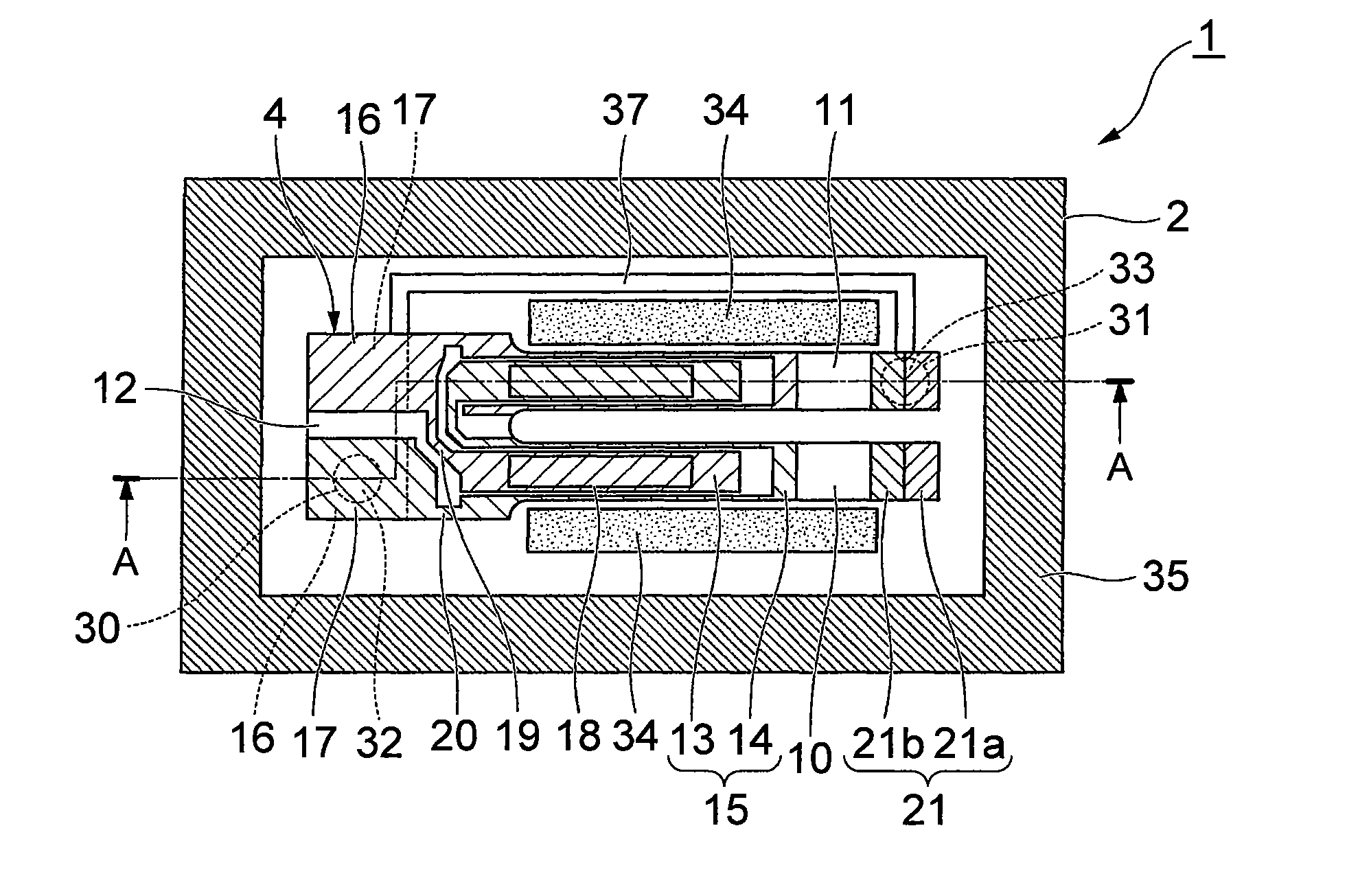
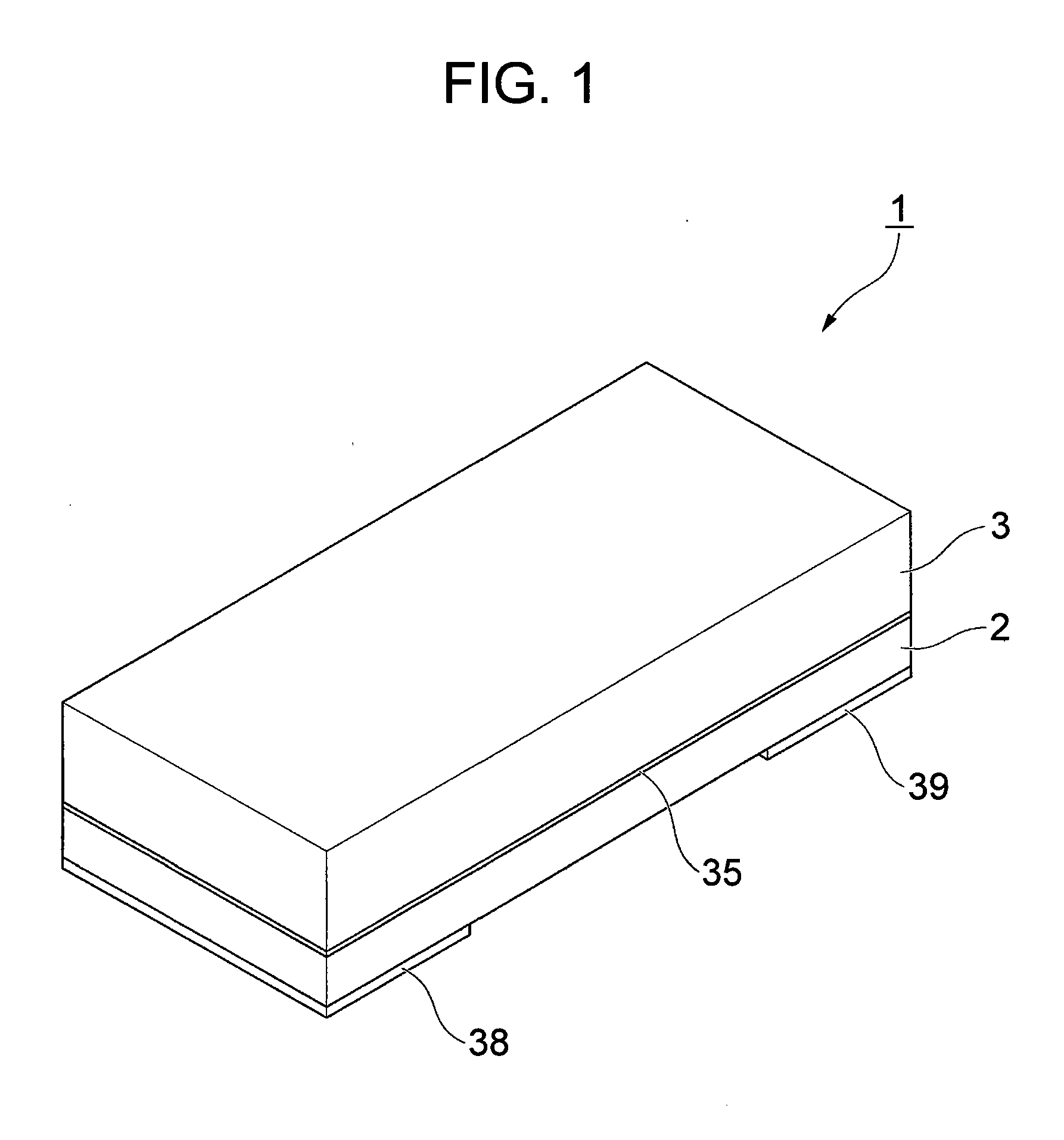
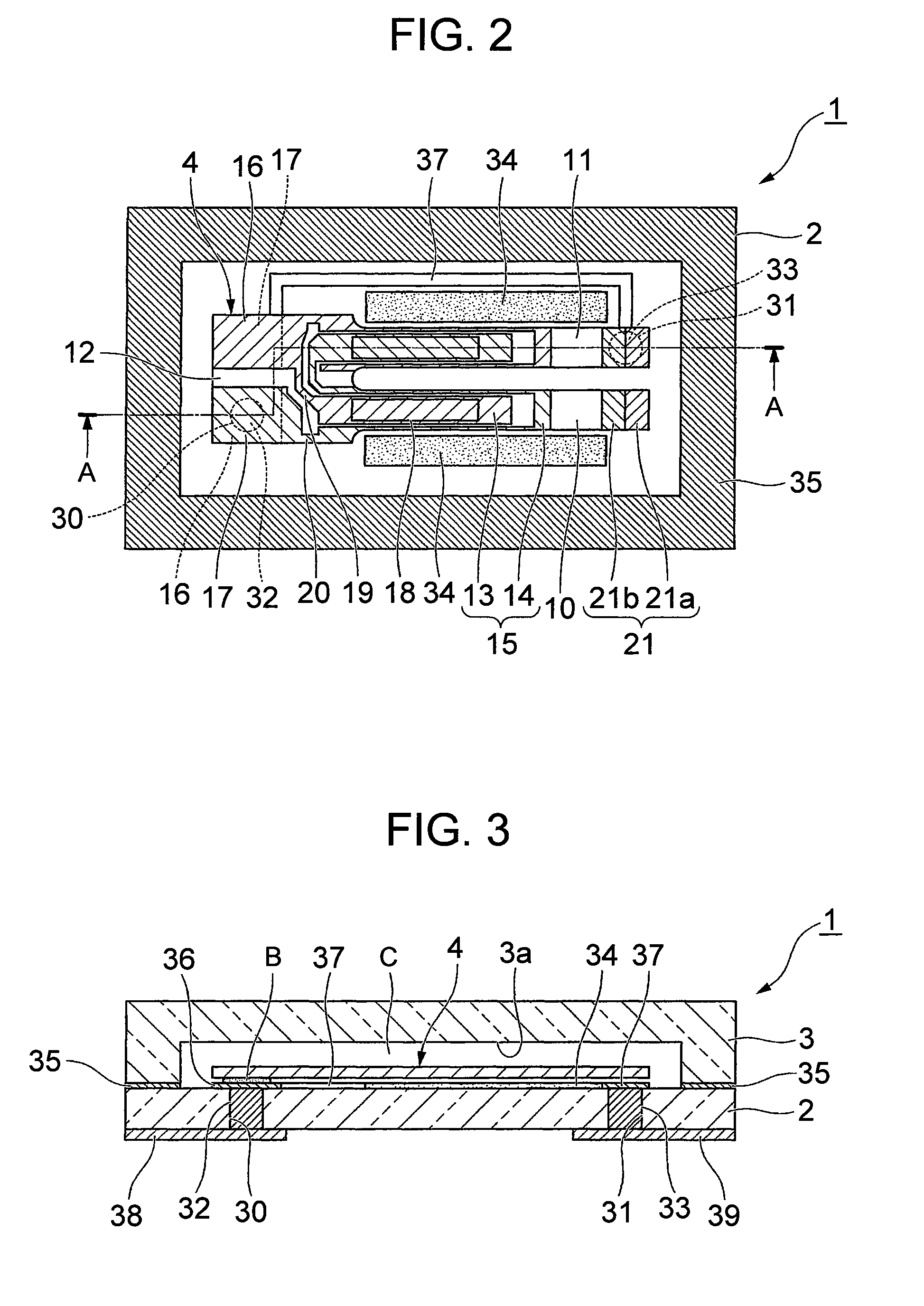
[0094]As illustrated in FIGS. 1 through 4, a piezoelectric transducer 1 according to this embodiment is a box-shaped device which has laminated two-layer structure constituted by a base substrate 2 and a lid substrate 3 as a surface mount device piezoelectric transducer containing a piezoelectric oscillation piece 4 in a cavity C formed inside the piezoelectric transducer 1.

[0095]For easy understanding of the figure, FIG. 4 does not show oscillation electrodes 15, extension electrodes 19 and 20, mount electrodes 16 and 17, and weight metal films 21 described later.

[0096]As illustrated in FIGS. 5 through 7, the piezoelectric oscillation piece 4 is a tuning-fork-type oscillation piece made of piezoelectric material such as crystal, lithium tantalate, and lithium niobate, and oscillates when predetermined voltage is applied.

[0097]The piezoelectric oscillation piece 4 includes a pair ...

second embodiment

[0145]Next, a second embodiment of the invention is hereinafter described with reference to FIG. 14. In the second embodiment, similar reference numbers are given to components similar to those in the first embodiment, and the same explanation is not repeated.

[0146]The second embodiment is different from the first embodiment in the getter members 34 formed in the control film forming step. While a pair of the getter members 34 are provided on the outside side surfaces of a pair of the oscillation arms 10 and 11 in the first embodiment, the getter member 34 is disposed between the pair of the oscillation arms 10 and 11 as viewed in the plan view in the second embodiment. That is, the getter member 34 is positioned in the vicinity of both the pair of the oscillation arms 10 and 11.

[0147]According to this embodiment, the advantages similar to those in the first embodiment can be offered, and the getter member 34 can be deposited on both side surfaces of the pair of the oscillation arms...

third embodiment

[0148]FIG. 19 is a perspective view illustrating the external appearance of a piezoelectric transducer according to an embodiment. FIG. 20 shows the internal structure of the piezoelectric transducer shown in FIG. 19, showing a piezoelectric oscillation piece from which a lid substrate is removed as viewed from above. FIG. 21 is a cross-sectional view of the piezoelectric transducer take along a line A-A in FIG. 20. FIG. 22 is a perspective view of the disassembled piezoelectric transducer. FIG. 22 does not show the oscillation electrodes 15, the extension electrodes 19 and 20, the mount electrodes 16 and 17, and the weight metal films 21 of the piezoelectric oscillation piece for easy understanding of the figure.

[0149]As illustrated in FIGS. 19 through 22, the piezoelectric transducer 1 in this embodiment is a surface mount device piezoelectric transducer 1 which includes a package 9 having laminated two layers of the base substrate 2 and the lid substrate 3, and the piezoelectric ...


PUM

PropertyMeasurementUnit
Weightaaaaaaaaaa
Lengthaaaaaaaaaa
Frequencyaaaaaaaaaa

Abstract

Provided are: a piezoelectric oscillation piece which has a pair of oscillation arms disposed in parallel with each other with base ends of the oscillation arms fixed to a base of the piezoelectric oscillation piece and with weight metal films formed at the tips of the oscillation arms; a base substrate on the upper surface of which the piezoelectric oscillation piece is mounted; a lid substrate joined with the base substrate such that the mounted piezoelectric oscillation piece can be accommodated in a cavity; and a control film disposed in the vicinity of the pair of the oscillation arms as viewed in the plan view and formed at least on either of the substrates in such a manner as to extend from the base end side to the tip side in the longitudinal direction of the oscillation arms for increasing the degree of vacuum inside the cavity by heating. The control film is locally deposited on the side surfaces of the oscillation arms in the vicinity of the control film by heating.

Description

RELATED APPLICATIONS[0001]This application is a continuation of PCT / JP2008 / 069109 filed on Oct. 22, 2008, which claims priority to Japanese Application Nos. 2008-035382 filed on Feb. 16, 2008 and 2008-163492 filed on Jun. 23, 2008. The entire contents of these applications are incorporated herein by reference.FIELD OF THE INVENTION[0002]The present invention relates to a surface mount device (SMD) piezoelectric transducer which has a piezoelectric oscillation piece sealed into a cavity formed between two joined substrates, a piezoelectric transducer manufacturing method for manufacturing the piezoelectric transducer, and an oscillator, an electronic device, and a radio clock each of which includes the piezoelectric transducer.BACKGROUND OF THE INVENTION[0003]Recently, a piezoelectric transducer containing crystal or the like as a time source, a timing source for generating control signals and others, or a reference signal source, for example, has been used in a cellular phone and a ...

Claims


Application Information

Patent Timeline
IPC IPC(8): H03B5/36H01L41/04H01L41/22
CPCH01L23/055H01L2924/01079H01L2924/3011H03H9/1021Y10T29/42H01L2924/0002H03H9/21H01L2924/00
Inventor FUKUDA, JUNYA
Owner SII CRYSTAL TECH
Why Eureka
Try Eureka