
Nuclear fuel arrangement in fuel pools for nuclear power plant

Inactive Publication Date: 2010-12-02
INST NUCLEAR ENERGY RES ROCAEC
View PDF5 Cites 0 Cited by
  • Summary
  • Abstract
  • Description
  • Claims
  • Application Information

AI Technical Summary

Benefits of technology

[0005]In view of the disadvantages of prior art, the object of the present invention is to provide a nuclear fuel arrangement in fuel pools for nuclear power plant capable of arranging the nuclear fuel bundles in the fuel pools in an improved formation for narrowing the distances between any two nuclear fuel bundles in the formation while meeting the optical safety requirement. In an embodiment, the present invention provides a nuclear fuel arrangement capable of arranging the nuclear fuel bundles in a rugged formation of different heights for reducing flux and effective multiplication factor of neutrons and thus causing the nuclear critical safety of the dry storage canister to be enhanced.
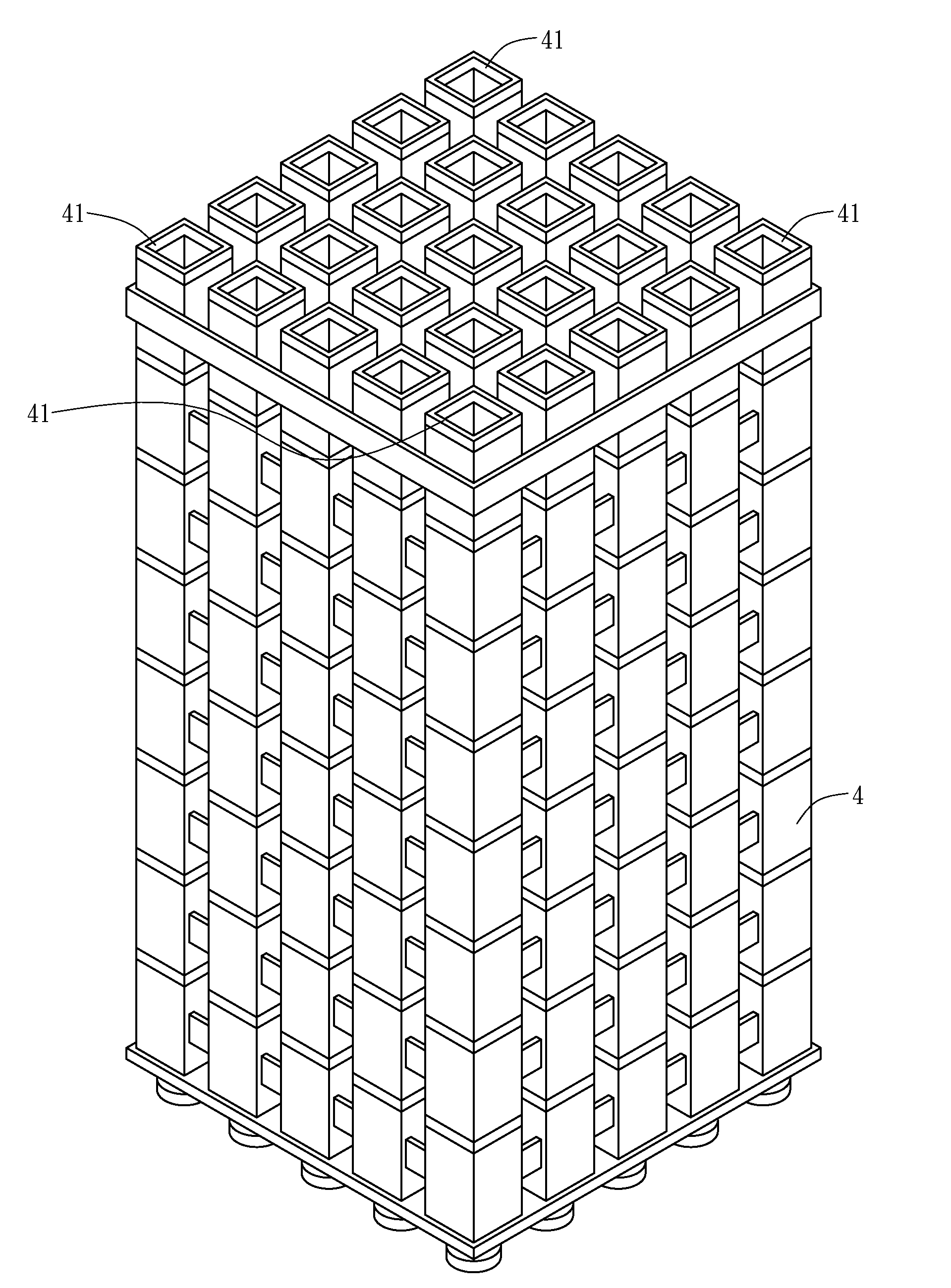
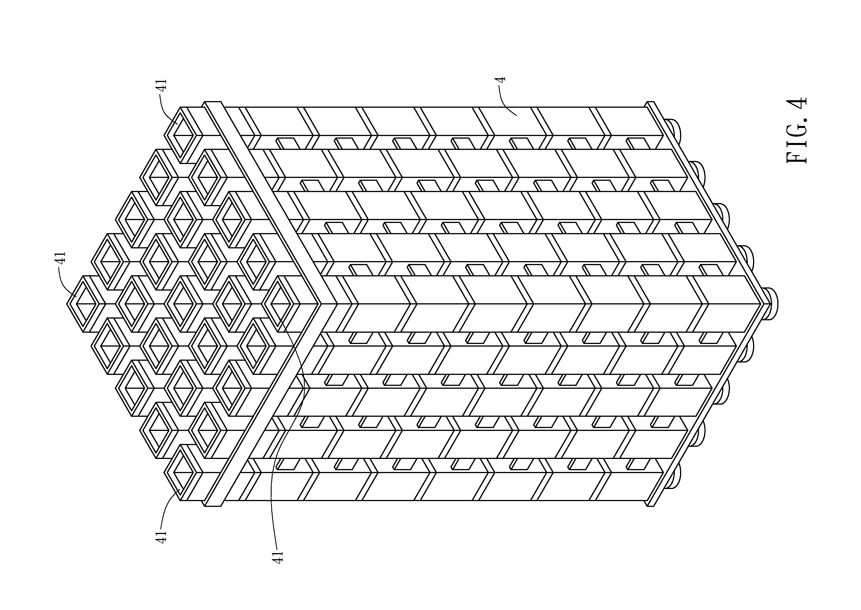
[0006]To achieve the above object, the present invention provides a nuclear fuel arrangement in fuel pools for nuclear power plant, which comprises: a plurality of nuclear fuel bundles, being arranged in a tight formation; a pool partition framework, formed with a plurality of grids for storing the plural nuclear fuel bundles; wherein the pool partition frame has a plurality of blocks of different heights disposed at the bottoms of their corresponding grids to be used for enabling any neighboring nuclear fuel bundles in the tight formation to be ruggedly arranged with different heights.

Problems solved by technology

The production of greenhouse gases and potential climate change is a problem of global proportion.
Normally, in most nuclear power plants, the fuel bundles as well as the spent fuel bundles are stored in fuel pools whereas the arrangement of the fuel bundles in the fuel pools is regulated for preventing those fuel bundle from being placed too close to each other and thus causing critical safety problem.
However, the use of boron piece will increase cost and the position arrangement / adjustment may be erroneous by human error, that both methods for increasing the amount of fuel bundles capable of being stored in a fuel pool still have shortcomings require to be improved.
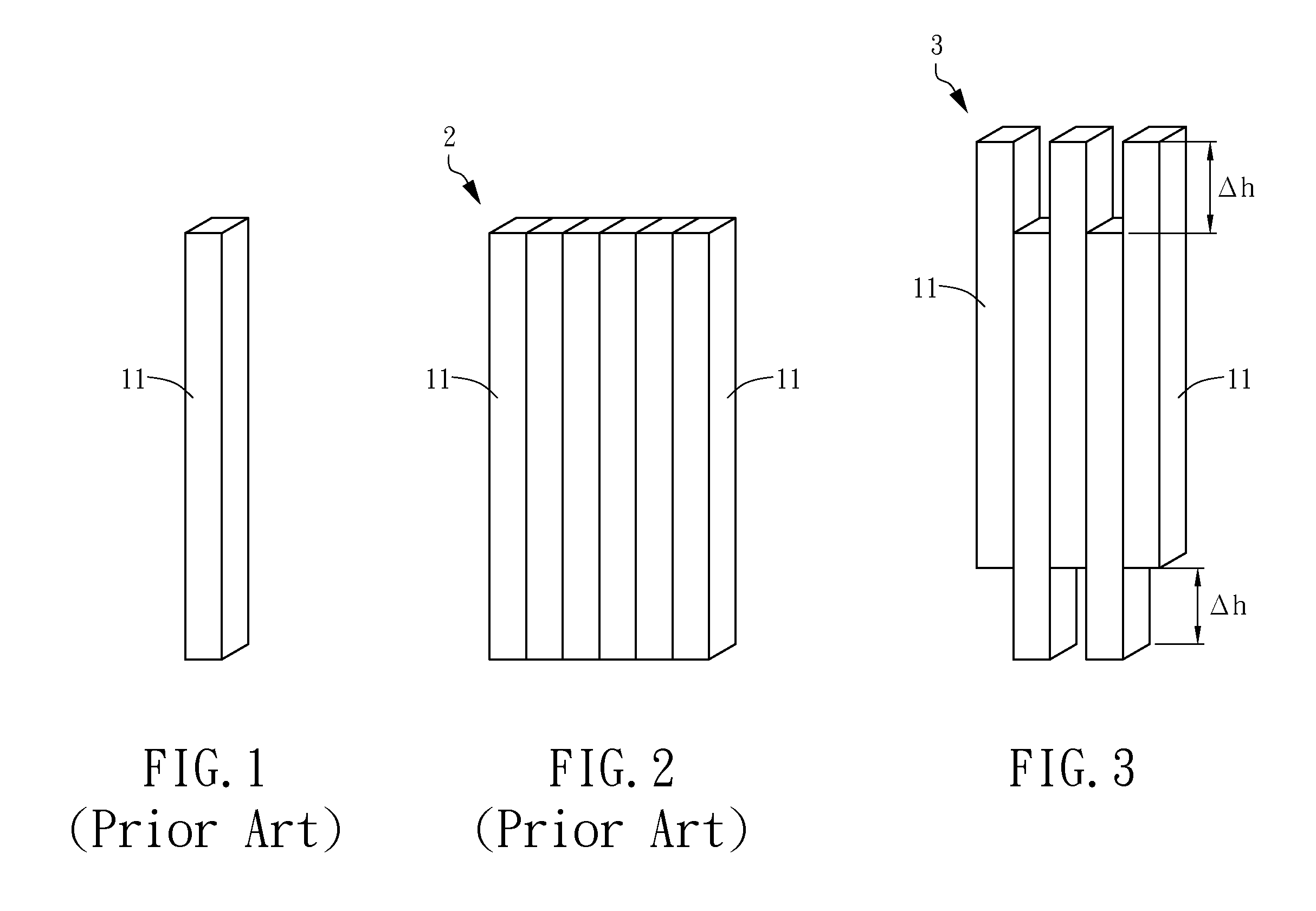
However, such neat formation 2 may not be the optimal formation regarding to nuclear fuel storage safety that should be improved.

Method used


Image

  • Nuclear fuel arrangement in fuel pools for nuclear power plant
  • Nuclear fuel arrangement in fuel pools for nuclear power plant
  • Nuclear fuel arrangement in fuel pools for nuclear power plant

Examples


Embodiment Construction

[0019]For your esteemed members of reviewing committee to further understand and recognize the fulfilled functions and structural characteristics of the invention, several exemplary embodiments cooperating with detailed description are presented as the follows.

[0020]Please refer to FIG. 3, which shows how the plural fuel bundles can be arranged ruggedly with different heights in a nuclear fuel arrangement in fuel pools for nuclear power plant of the invention. In FIG. 3, there is a plurality of nuclear fuel bundles 11 being lined up in a rugged formation 3 with a height difference Δh ranged between 3 inches to 12 inches. It is noted that when the height difference Δh is too large, the rugged formation 3 of the plural nuclear fuel bundles may not be received inside a pool partition framework in the fuel pool easily and thus a larger pool partition framework may be required; on the other hand, when the height difference Δh is too small, the requirement matching nuclear critical safety...


PUM


Abstract

A nuclear fuel arrangement in fuel pools for nuclear power plant is disclosed, which comprises: a plurality of nuclear fuel bundles, being arranged in a tight formation; a pool partition framework, formed with a plurality of grids for storing the plural nuclear fuel bundles; wherein the partition frame has a plurality of blocks of different heights disposed at the bottoms of their corresponding grids to be used for enabling any neighboring nuclear fuel bundles in the tight formation to be ruggedly arranged with different heights.

Description

FIELD OF THE INVENTION[0001]The present invention relates to a nuclear fuel arrangement in fuel pools for nuclear power plant, and more particularly, to a fuel arrangement for a fuel pool capable of arranging nuclear fuel bundles in a rugged formation of different heights for reducing flux and effective multiplication factor of neutrons and thus causing the nuclear critical safety of the fuel pool to be enhancedBACKGROUND OF THE INVENTION[0002]The production of greenhouse gases and potential climate change is a problem of global proportion. Man's use of energy, especially in industrial activity with fossil fuel burning that emits gases containing carbon dioxide, is thought by most experts to be the major contributor to greenhouse effect responsible for climate change. Thus, people all over the world are searching for alternative energies as they are aiming to live in a greener and more energy efficient lives. Among those available alternative energies, as nuclear power can provide e...

Claims


Application Information

Patent Timeline
IPC IPC(8): G21C3/34
CPCG21C19/07Y02E30/30
Inventor YEH, JAU-TYNESUNG, TA-LUNHU, CHUNG-HSINGYAUR, SHYUN-JUNG
Owner INST NUCLEAR ENERGY RES ROCAEC
Learn More