Tool holder and cutting insert with centering nose portion

a tool holder and cutting insert technology, applied in boring/drilling equipment, turning equipment, milling equipment, etc., can solve the problems of unsatisfactory registration, unfavorable registration, and unwanted debris stuck to either one of the v-shaped surfaces, so as to reduce the risk of imperfect registration

Inactive Publication Date: 2010-12-02
SAFETY SA
View PDF8 Cites 12 Cited by
  • Summary
  • Abstract
  • Description
  • Claims
  • Application Information

AI Technical Summary

Benefits of technology

[0007]The present invention sets out to provide a solution making it possib

Problems solved by technology

The first cause is related to some fault in clamping the insert, and it is relatively easy to design effective clamping mechanisms.
Further, any unwanted d

Method used


Image

  • Tool holder and cutting insert with centering nose portion
  • Tool holder and cutting insert with centering nose portion
  • Tool holder and cutting insert with centering nose portion

Examples


Embodiment Construction

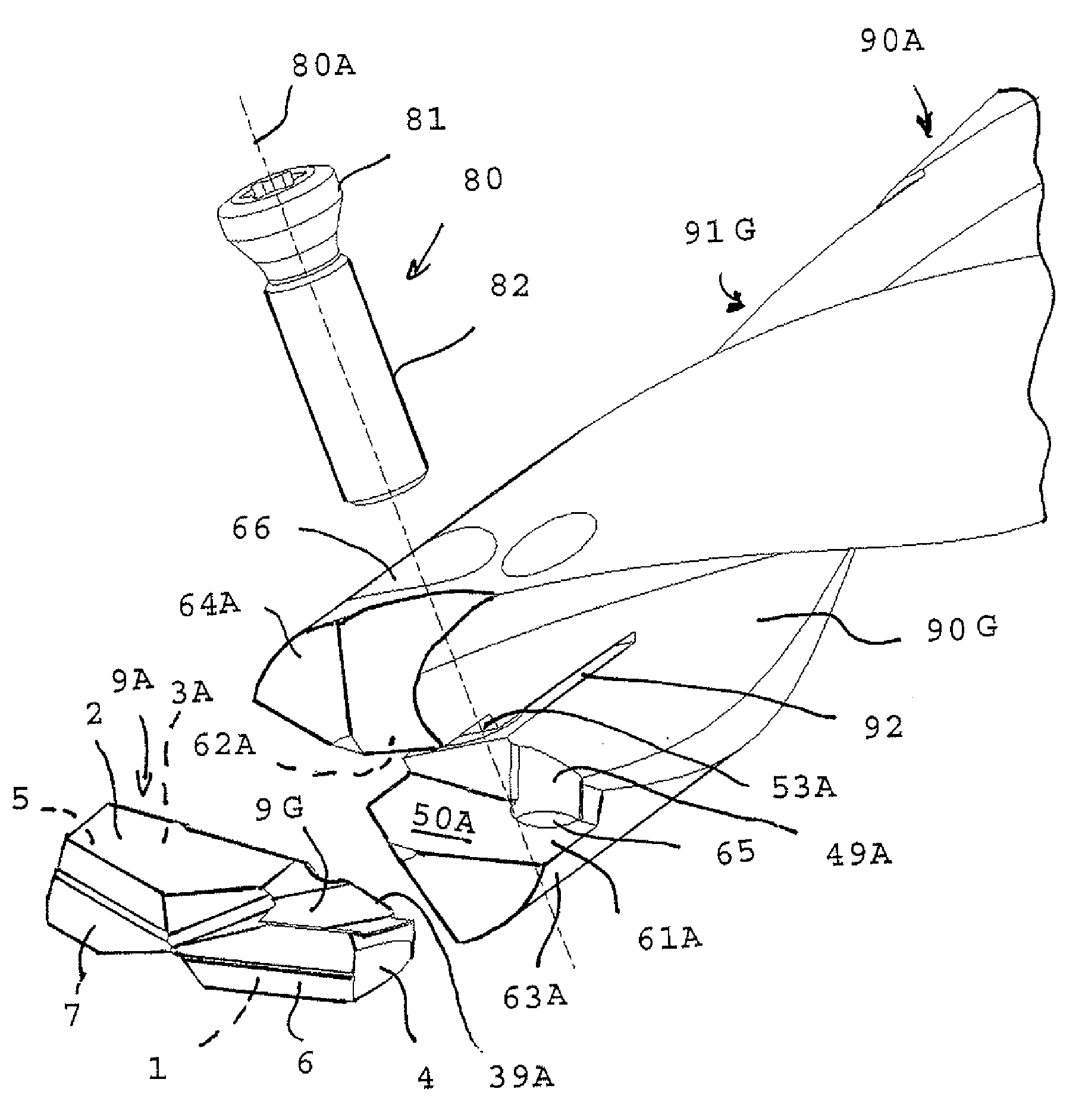
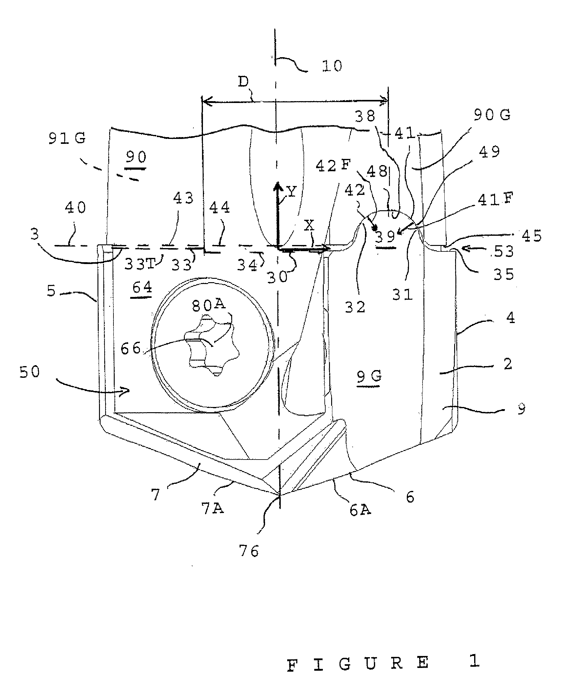
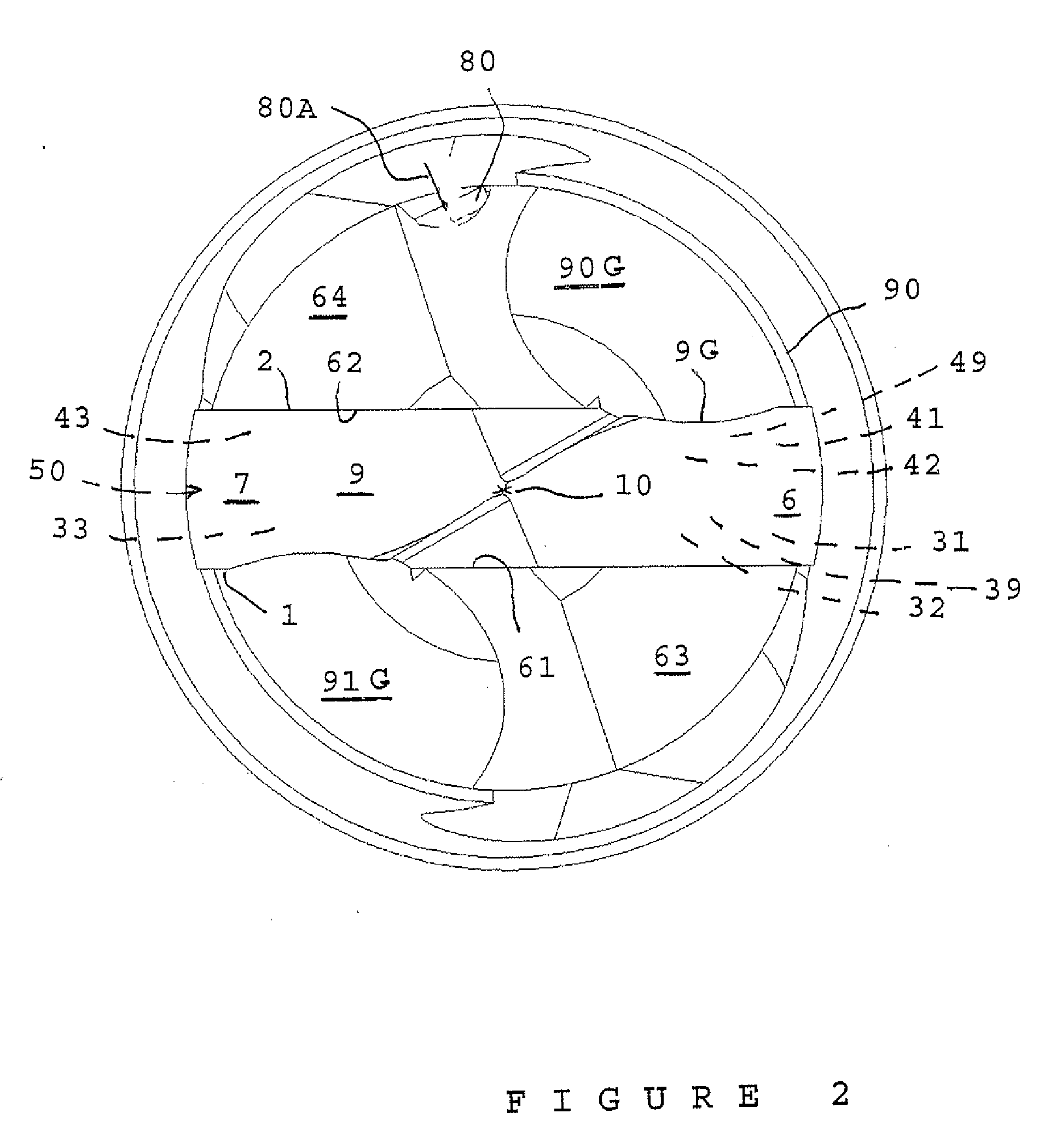
[0033]The drill bit shown partially in FIGS. 1, 2 and 3 comprises a shaft 90, with geometric axis of rotation 10, there only being shown an end portion thereof which includes a pocket 50 in the form of a forwardly-open, i.e. in the direction of the bottom of FIG. 1, diametrical slot.

[0034]Unless otherwise stated, in this description, references to axial or radial orientation are with reference to axis 10. Similarly, the “forward” direction herein is the functional direction of the drill bit, in other words a direction running from its rear end towards its forward end, that includes pocket 50.

[0035]As can be seen better in FIGS. 2 and 3, pocket 50 of FIG. 1 is limited by two major lateral clamping surfaces 61 and 62 which are parallel and here axial, respectively belonging to two slightly flexible cheeks or jaws 63, 64, symmetrically opposed with respect to axis 10. When fitting a cutting insert 9 into shaft 90, the user will typically employ clamping surface 61 as a bearing surface,...


PUM

PropertyMeasurementUnit
Fractionaaaaaaaaaa
Fractionaaaaaaaaaa
Angleaaaaaaaaaa

Abstract

The cutting tip comprises a lateral face for aligned lateral positioning against a lateral alignment line with a tool holder housing, comprising an alignment snout with first and second lateral alignment surfaces that bear respectively against first and second lateral driving alignment surfaces and comprising, at some distance, a third lateral alignment surface for bearing against a third lateral driving alignment wall surface, two out of the first, second and third alignment surfaces being mutually inclined in such a way as to ensure alignment in a chosen position of travel with respect to the driving lateral wall surfaces opposite.

Description

FIELD OF THE INVENTION[0001]The present invention relates to cutting inserts, and in particular their mounting on carrier tool.BACKGROUND OF THE INVENTION[0002]If we consider for example the case of a drill, the associated cutting insert is received inside a pocket in the form of a slot forwardly open in diametrical position. The cutting insert usually has an overall spearpoint shape, that is a diamond shape with two forwardly directed male V-shaped lateral faces, centered on the geometrical axis of rotation of the drill, and two lateral male V-shaped faces similarly centered and backwardly directed.[0003]The two forward lateral faces each define, together with one respective major face of the cutting insert, two V-shaped male cutting edges, considered in plan view, and the two rear positioning lateral faces are used for registering by back abutment against two similarly V-shaped female registering walls of the pocket.[0004]The insert is firmly held in the desired registered positio...

Claims


Application Information

Patent Timeline
IPC IPC(8): B23P15/28B26D3/00
CPCB23B27/1622B23B51/0009B23B51/02B23B2200/161B23B2205/12B23B2251/02B23C5/2221Y10T407/2272Y10T407/23B23B51/00035B23C5/2213
Inventor FOUQUER, RICHARD
Owner SAFETY SA
Why Eureka
Try Eureka