Fan Drive System
a technology of fan drive and drive shaft, which is applied in the direction of positive displacement liquid engine, machine/engine, servomotor, etc., can solve the problems of consuming a lot of space, reducing and limiting the layout degree of the radiator and other devices, so as to prevent the waste of discharge flow rate and reduce the displacement of the hydraulic pump.
- Summary
- Abstract
- Description
- Claims
- Application Information
AI Technical Summary
Benefits of technology
Problems solved by technology
Method used
Image

Examples
first embodiment
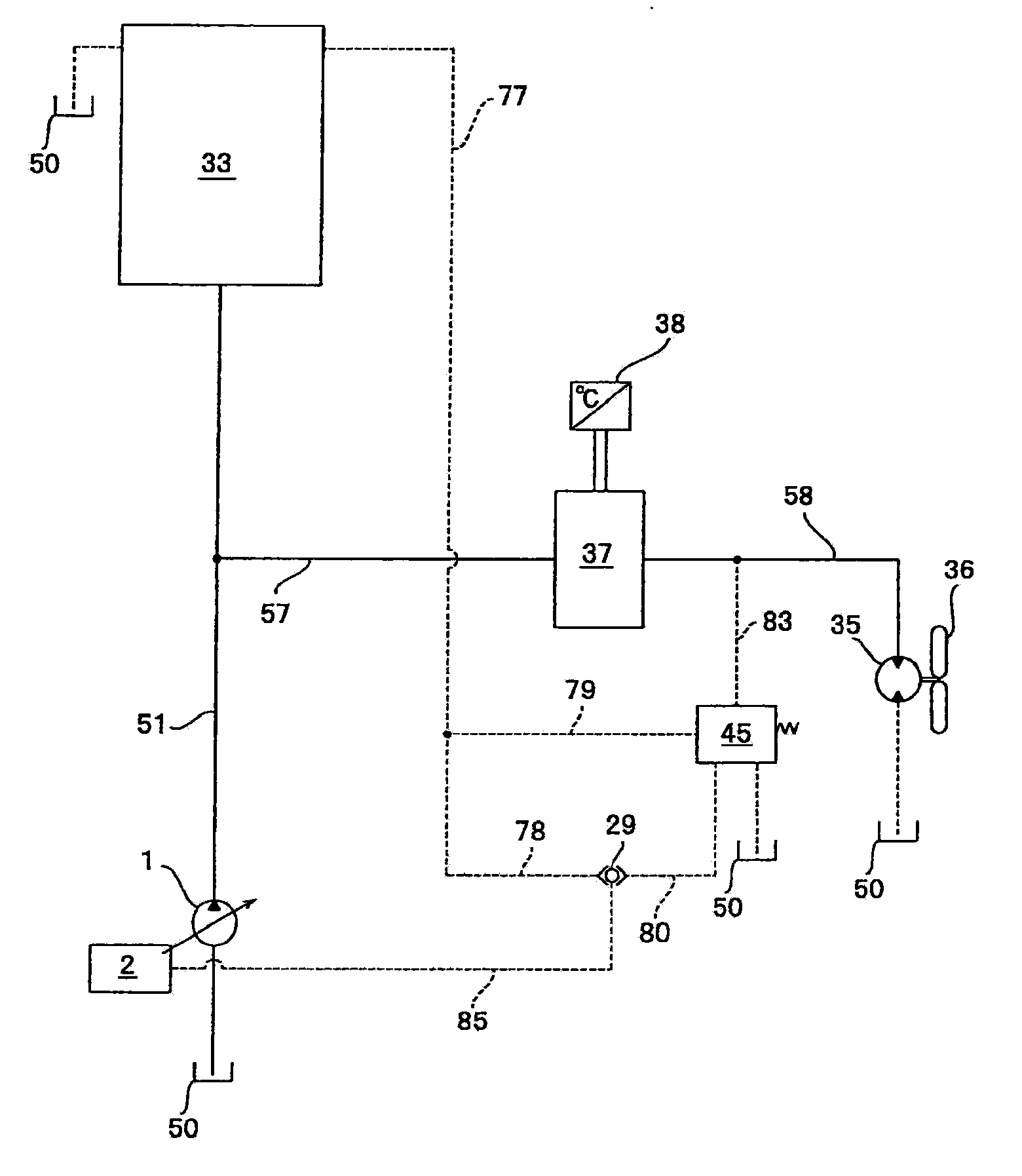
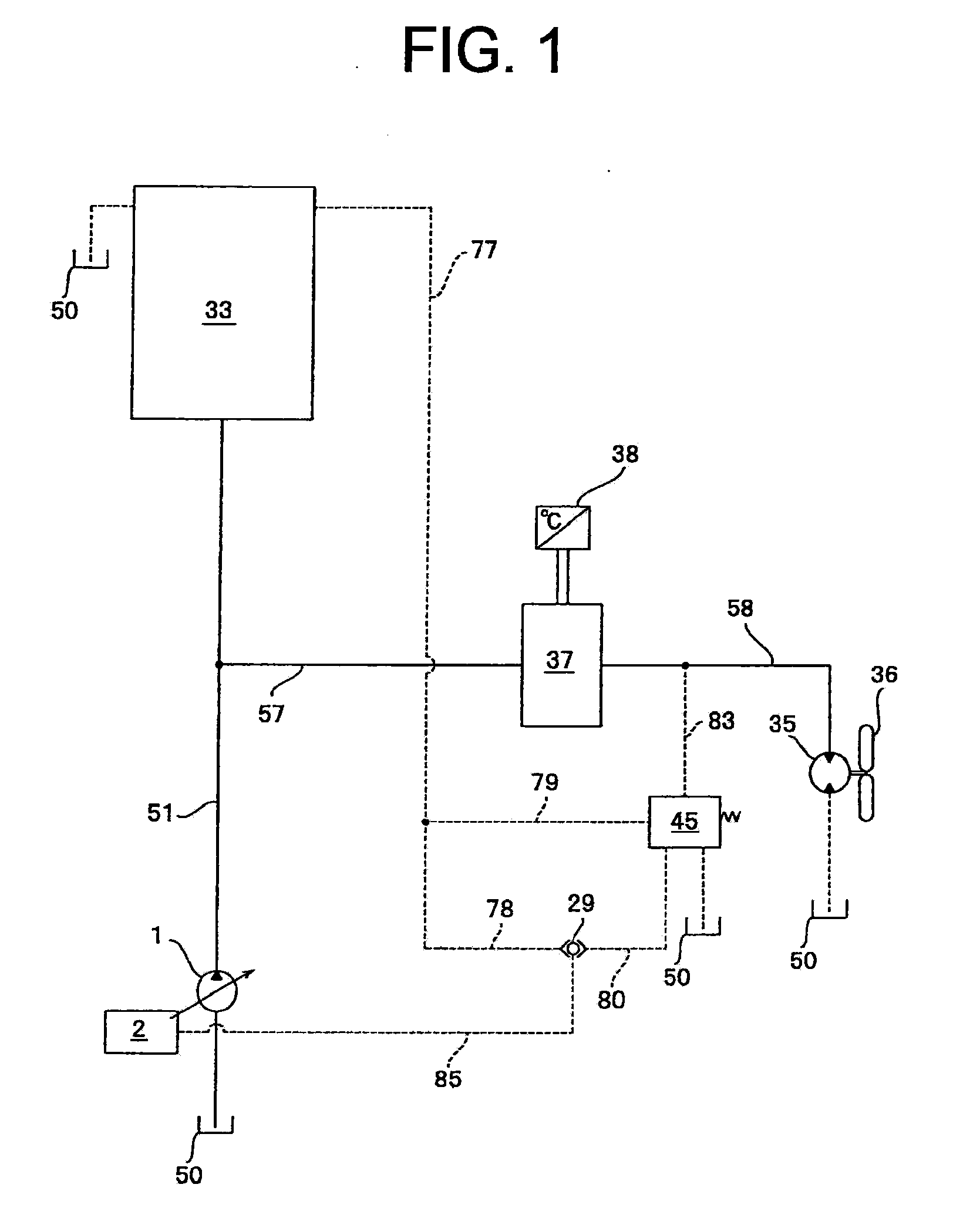
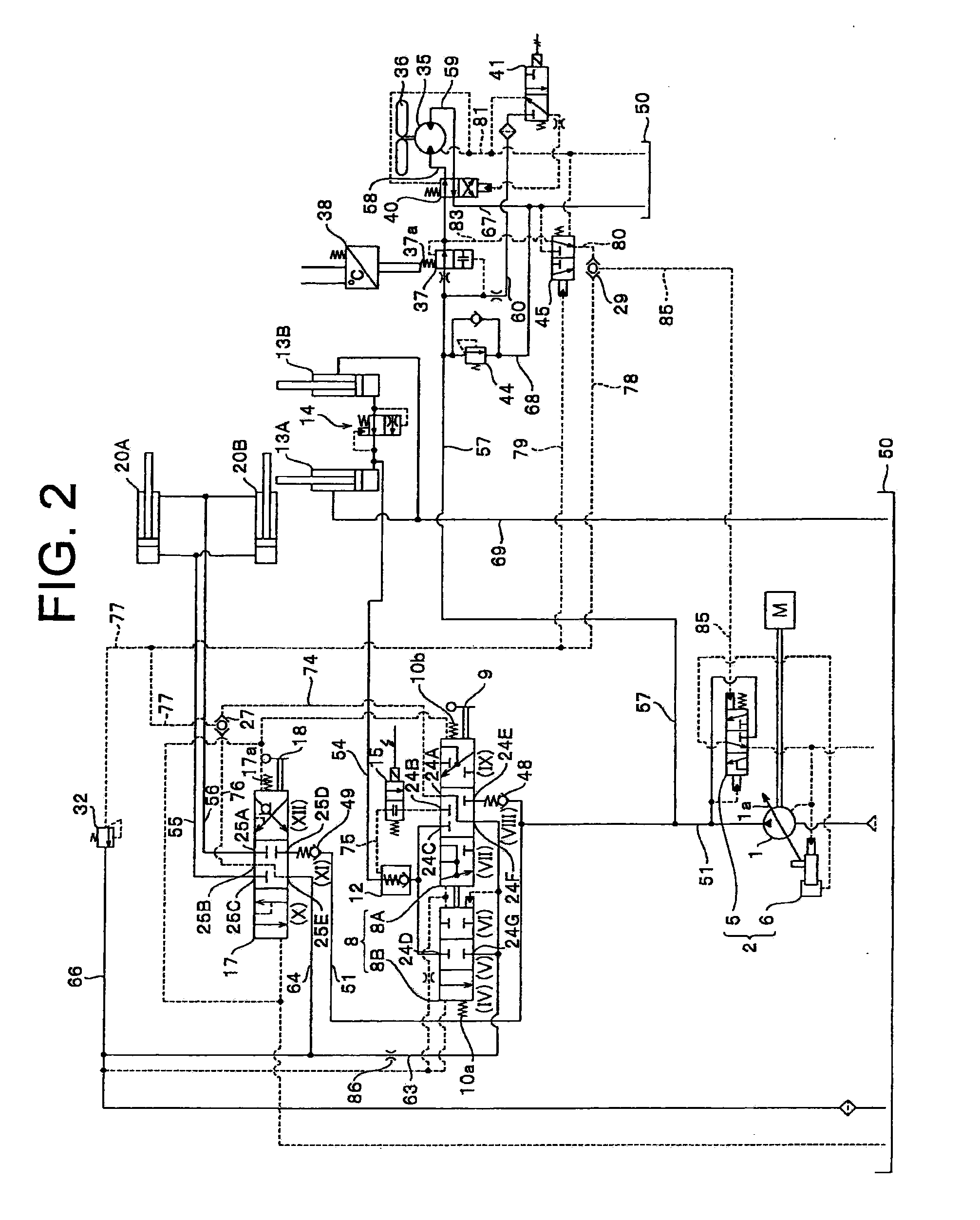
[0086]A hydraulic circuit having a fan drive system according to the First embodiment of the present invention will be explained using FIGS. 1 and 2. FIG. 1 is a simplified hydraulic circuit diagram and FIG. 2 is a detailed hydraulic circuit diagram. First, the hydraulic circuit having the fan drive system according to the First embodiment of the invention will be briefly explained using FIG. 1 and then, the hydraulic circuit having the fan drive system according to the First embodiment of the invention will be explained using FIG. 2. Numbers of common members in FIGS. 1 and 2 will be explained using the same numbers of members.
[0087]As shown in FIG. 1, a discharge flow rate from a load pressure sensitive variable displacement pump 1 which is driven by an engine (not shown) is discharged to a discharge oil path 51 as a first discharge oil path. The discharge oil path 51 is branched into an oil path 57 as a second discharge oil path. The discharge oil path 51 is connected to a workin...
second embodiment
[0151]A hydraulic circuit having a fan drive system according to the Second embodiment of the present invention will be explained using FIGS. 3 and 4. The Second embodiment has a steering drive circuit in addition to the hydraulic circuit of the First embodiment. Maximum one of load pressures of a steering drive device 30, the lift cylinders 13A and 13B and the tilt cylinders 20A and 20B is used ad a load pressure in the pilot oil path 78 as a first pilot oil path which is led to the shuttle valve 29. In this structure, the Second embodiment is different from the First embodiment, but other structure is the same as that of the First embodiment.
[0152]Therefore, members of the Second embodiment which are the same as those of the First embodiment are designated with the same reference numerals, and explanation thereof will be omitted, and a structure which is different from that of the First embodiment will be explained mainly. The pilot oil path 78 connected to the shuttle valve 29 is...
third embodiment
[0186]FIGS. 5 and 6 show a hydraulic circuit having a fan drive system according to the Third embodiment of the present invention. A circuit structure for leading a load pressure to the pilot oil path 80 in the Third embodiment is different from those of the First and Second embodiments. Other structure is similar to the circuit structure shown in FIG. 2 that is a circuit structure of the First embodiment in FIG. 5, and other structure is similar to the circuit structure shown in FIG. 4 that is a circuit structure of the Second embodiment in FIG. 6
[0187]Concerning FIG. 5 where the priority valve 3 is not disposed, the same structure as that of the First embodiment and the same members of the Third embodiment which are the same as those of the First embodiment are designated with the same reference numerals, and explanation thereof will be omitted. Concerning FIG. 6 where the priority valve 3 is used, the same structure as that of the Second embodiment and the same members of the Thi...
PUM
 Abstract
Description
Claims
Application Information
 - R&D
- Intellectual Property
- Life Sciences
- Materials
- Tech Scout
- Unparalleled Data Quality
- Higher Quality Content
- 60% Fewer Hallucinations
Browse by: Latest US Patents, China's latest patents, Technical Efficacy Thesaurus, Application Domain, Technology Topic, Popular Technical Reports.
© 2025 PatSnap. All rights reserved.Legal|Privacy policy|Modern Slavery Act Transparency Statement|Sitemap|About US| Contact US: help@patsnap.com