Exposure apparatus, exposure method, and device manufacturing method

a technology of exposure apparatus and manufacturing method, which is applied in the direction of microlithography exposure apparatus, printers, instruments, etc., can solve the problems of defective device manufacturing, exposure failure, and member coming into contact with liquid, so as to suppress the failure of exposure and suppress the failure of defective devi

Active Publication Date: 2010-12-02
NIKON CORP
View PDF33 Cites 27 Cited by
  • Summary
  • Abstract
  • Description
  • Claims
  • Application Information

AI Technical Summary

Benefits of technology

[0031]According to the above-mentioned aspects of the invention, it is possible to suppress an exposure failure from occ

Problems solved by technology

In an immersion exposure apparatus, a member coming in contact with a liquid may be contaminated.
For example, when a foreign material is attached to the member, defects are caused in a pattern formed on the substrate, thereby causing an exposure failure.
As a result, a defective device may be manufactured.
In the immersion exposure apparatus, for example, when the substrate is mov

Method used


Image

  • Exposure apparatus, exposure method, and device manufacturing method
  • Exposure apparatus, exposure method, and device manufacturing method
  • Exposure apparatus, exposure method, and device manufacturing method

Examples


first embodiment

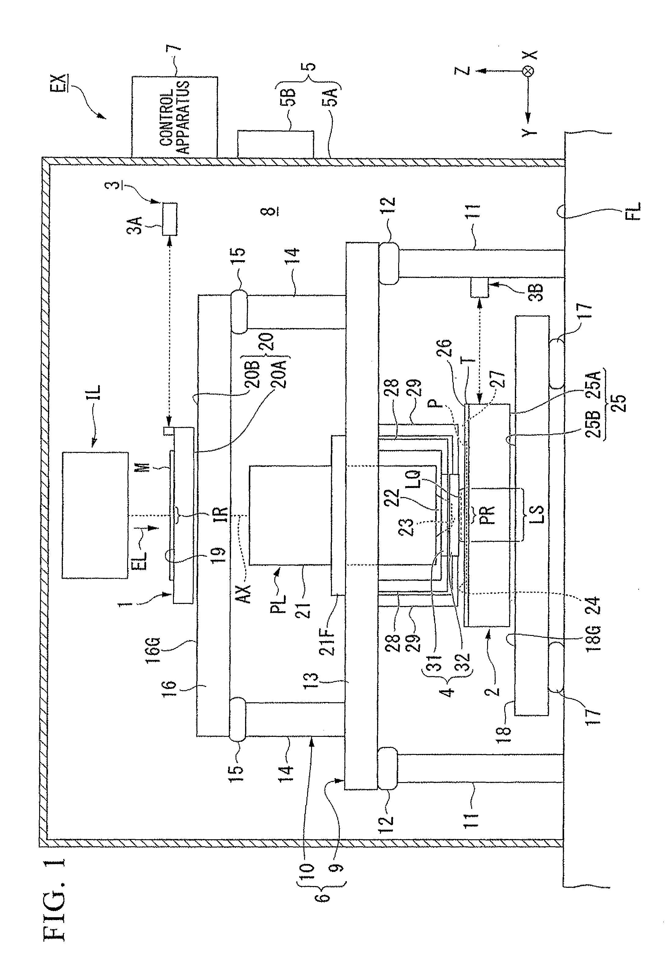
[0063]A first embodiment of the invention will be described. FIG. 1 is a diagram schematically illustrating a configuration of an exposure apparatus EX according to the first embodiment of the invention. The exposure apparatus EX according to this embodiment is an immersion exposure apparatus exposing a substrate P with an exposure light (exposure light beam) EL via a liquid LQ. In this embodiment, water (pure water) is used as the liquid LQ.

[0064]In FIG. 1, the exposure apparatus EX includes a mask stage 1 which can move with a mask M held thereon, a substrate stage 2 which can move with a substrate P held thereon, an interferometer system 3 optically measuring positions of the mask stage 1 and the substrate stage 2, an illumination system IL illuminating the mask M with an exposure light EL, a projection optical system PL projecting an image of a pattern of the mask M illuminated with the exposure light EL onto the substrate P, an immersion member 4 forming an immersion space LS s...

second embodiment

[0156]A second embodiment of the invention will be described below. In the following description, the elements equal or equivalent to those of the above-mentioned embodiment are referenced by like reference numerals and signs, and are described in brief or are not repeatedly described.

[0157]FIG. 6 is a diagram illustrating an example of an immersion member 4B according to the second embodiment of the invention. In FIG. 6, the immersion member 4B includes a first member 31B having a first surface 41, a second member 32 having a second surface 42, and a third member 82 which is different from the first member 31B and the second member 32 and which includes a recovery port 62 and a porous member 64. The third member 82 can be detached from the first member 31B.

[0158]The third member 82 includes a body portion 82A and a flange portion 82B disposed at the top end of the body portion 82A. The body portion 82A can be disposed in an aperture 83A disposed in the first member 31B. The flange ...

third embodiment

[0161]A third embodiment of the invention will be described below. In the following description, the elements equal or equivalent to those of the above-mentioned embodiment are referenced by like reference numerals and signs, and are described in brief or are not repeatedly described.

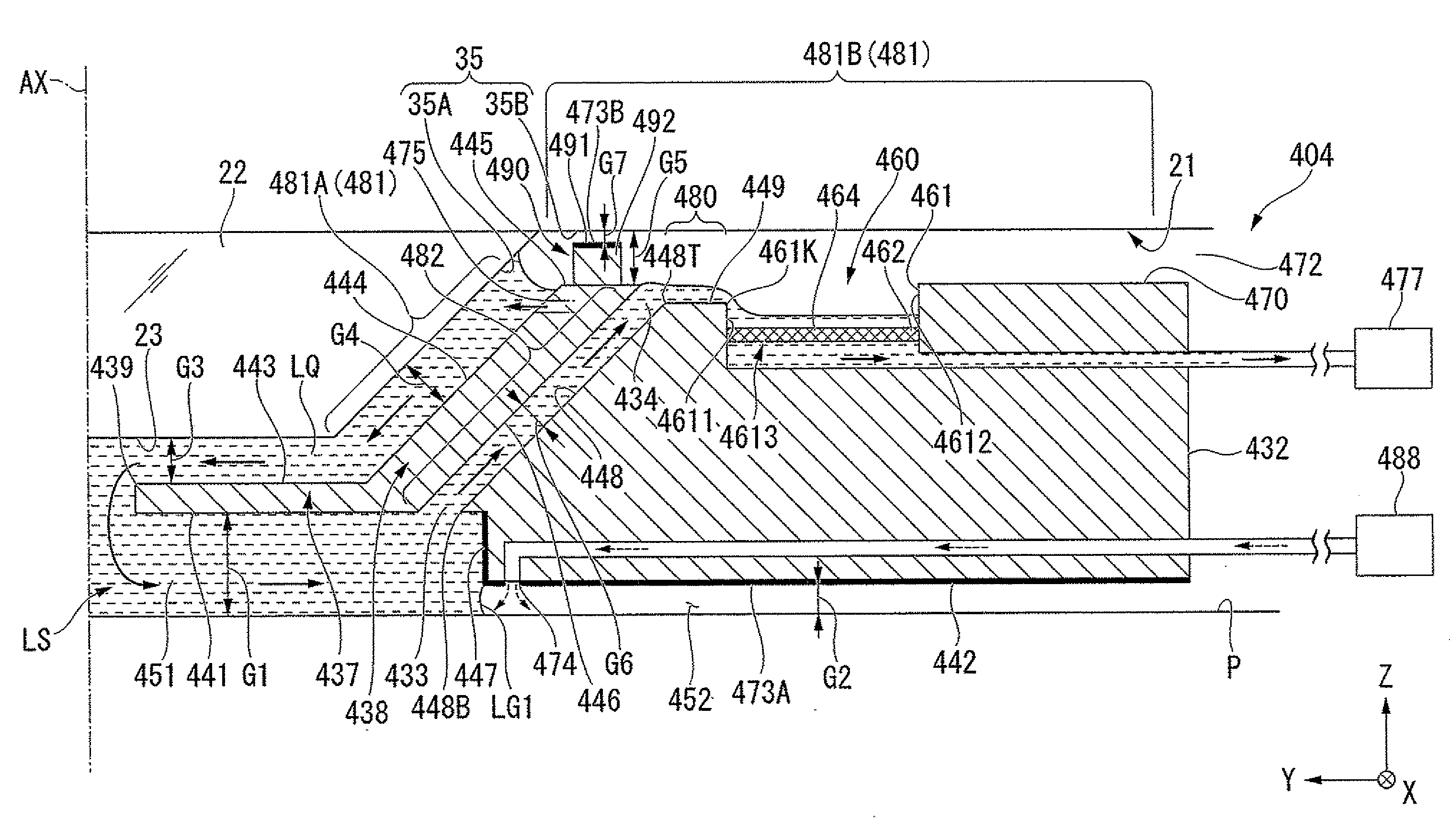
[0162]FIG. 7 is a diagram illustrating an example of an immersion member 4C according to the third embodiment of the invention. In FIG. 7, the immersion member 4C includes a first member 31C having the first surface 41 and a second member 32C having the second surface 42. A first recovery portion 60C includes a first recess portion 61C disposed in the second member 32C and a recovery port 62C recovering the liquid LQ flowing into the first recess portion 61C. This embodiment is different from the first and second embodiments, in that the recovery port 62C is disposed in the first recess portion 61C but the second member 32C includes the recovery port 62C and a part of a recovery flow channel. In this em...


PUM


Abstract

An exposure apparatus that exposes a substrate includes: an optical system that includes an emission surface from which an exposure light is emitted; a first surface that is disposed in at least a part of a surrounding of an optical path of the exposure light emitted from the emission surface; a second surface that is disposed in at least a part of a surrounding of the first surface and at a position lower than the first surface; a space portion into which a liquid can flow via a first aperture between the first surface and the second surface and which is opened to the atmosphere via a second aperture different from the first aperture; and a first recovery portion that recovers at least a part of the liquid flowing into the space portion. Here, the emission surface, the first surface, and the second surface are opposed to the surface of the substrate in at least a part of the exposure of the substrate, and the substrate is exposed with the exposure light from the emission surface via the liquid between the emission surface and the surface of the substrate.

Description

CROSS-REFERENCE TO RELATED APPLICATION[0001]This application is a non-provisional application claiming priority to and the benefit of U.S. provisional Application Nos. 61 / 193,833, 61 / 193,834, 61 / 193,835, and 61 / 193,836, filed Dec. 29, 2008, the contents of which are incorporated herein by reference.BACKGROUND[0002]1. Field of the Invention[0003]The present invention relates to an exposure apparatus, an exposure method, and a device manufacturing method.[0004]2. Description of Related Art[0005]In the processes of manufacturing a micro device such as a semiconductor device and an electronic device, an immersion exposure apparatus exposing a substrate with an exposure light from a projection optical system via a liquid between the projection optical system and the substrate is known, examples of which are disclosed in U.S. Patent Application Publication Nos. 2006 / 0221315, 2007 / 0081140, and 2008 / 0174748.SUMMARY[0006]In an immersion exposure apparatus, a member coming in contact with a l...

Claims


Application Information

Patent Timeline
IPC IPC(8): G03F7/20G03B27/52
CPCG03F7/70916G03F7/70341G03F7/2041
Inventor SATO, SHINJI
Owner NIKON CORP
Why Eureka
Try Eureka