Hitting position detecting device, hitting position detecting method, and method of manufacturing hitting position detecting device

a technology of hitting position and detecting device, which is applied in the field hitting position detecting method, and manufacturing of hitting position detecting device, can solve the problems of inability to achieve the desired effect, and increased equipment size, etc., to achieve excellent accuracy and reliability, improve durability, and improve the effect of accuracy

Inactive Publication Date: 2010-12-02
MUGEN
View PDF18 Cites 86 Cited by
  • Summary
  • Abstract
  • Description
  • Claims
  • Application Information

AI Technical Summary

Benefits of technology

[0121](1) The ball hitting position can be clearly determined. That is, the determination of the ball hitting position can be excellently conducted.
[0122](2) The present invention is proved on the basis of a plurality of hitting results (the practical value of the numeral equations is acknowledged).
[0123](3)

Problems solved by technology

It has been thought for a long time that the desire (problem) has not been practically solved or embodied despite many trials and suggestions since there is no information on the practical technology/method for the embodiment thereof and the accuracy thereof (recognition of existence of long-term unresolved problems).
There have been merely desires, but no complete disclosures containing contents including the practical accuracy based on “specific experiments” such as the arrangement position of sensors having a certain function, a timing of generating a certain calling signal, a calculation process, a display position, a certain display manner/shape, and a correct process through experiments (a long-term unresolved problem).
Meanwhile, although a method of imaging the golf club using a high-speed camera is a reliable method, the cost increases due to an increase in the size of the equipment.
In addition, since the camera needs to be installed before the ball to shoot the flying ball after hitting, the photographer is in great danger due to the ball flying before him/her, and the camera needs to be protected so that the camera is not broken.
Such are the critical defects of this method (critical defects of solving means).
This method has critical defects in that it is necessary to perform an operation of attaching the sheet to the face portion of the club and detaching the sheet after usage every time, the repeated consumption of the pressure sheets is bothersome, and the hitting feeling is different for each sheet (critical defects of solving means).
In addition, there have been attempts to compare and display the repeated swing actions, but the display of the hitting position of the face portion has not been successful.
For this reason, it is not possible to sufficiently display the hitting position with a high accuracy only by using an “accelerometer” (a long-term unresolved problem).
Accordingly, this method is not effective for specifying the hitting position of the golf club (unsuitableness of means).
In this method, equipment needs to be prepared below a ball to be hit, the equipment is dependent on many types of largely different clubs, the data for each hitting position is not clear, and simplicity is degraded due to an excessive increase in size of the equipment involved.
Although this method can be used in the measurement of sports such as golf or a pitcher's pitching practice, it should be noted that the impact generated upon hitting of the golf ball is of extremely high pressure.
Then, regardless of the installation positions of the layers, th

Method used


Image

  • Hitting position detecting device, hitting position detecting method, and method of manufacturing hitting position detecting device
  • Hitting position detecting device, hitting position detecting method, and method of manufacturing hitting position detecting device
  • Hitting position detecting device, hitting position detecting method, and method of manufacturing hitting position detecting device

Examples


embodiments

[0289]Hereinafter, the present invention will be described in more detail with reference to the embodiments. However, the effectiveness of the present invention is not considered as being limited by the embodiments.

first embodiment

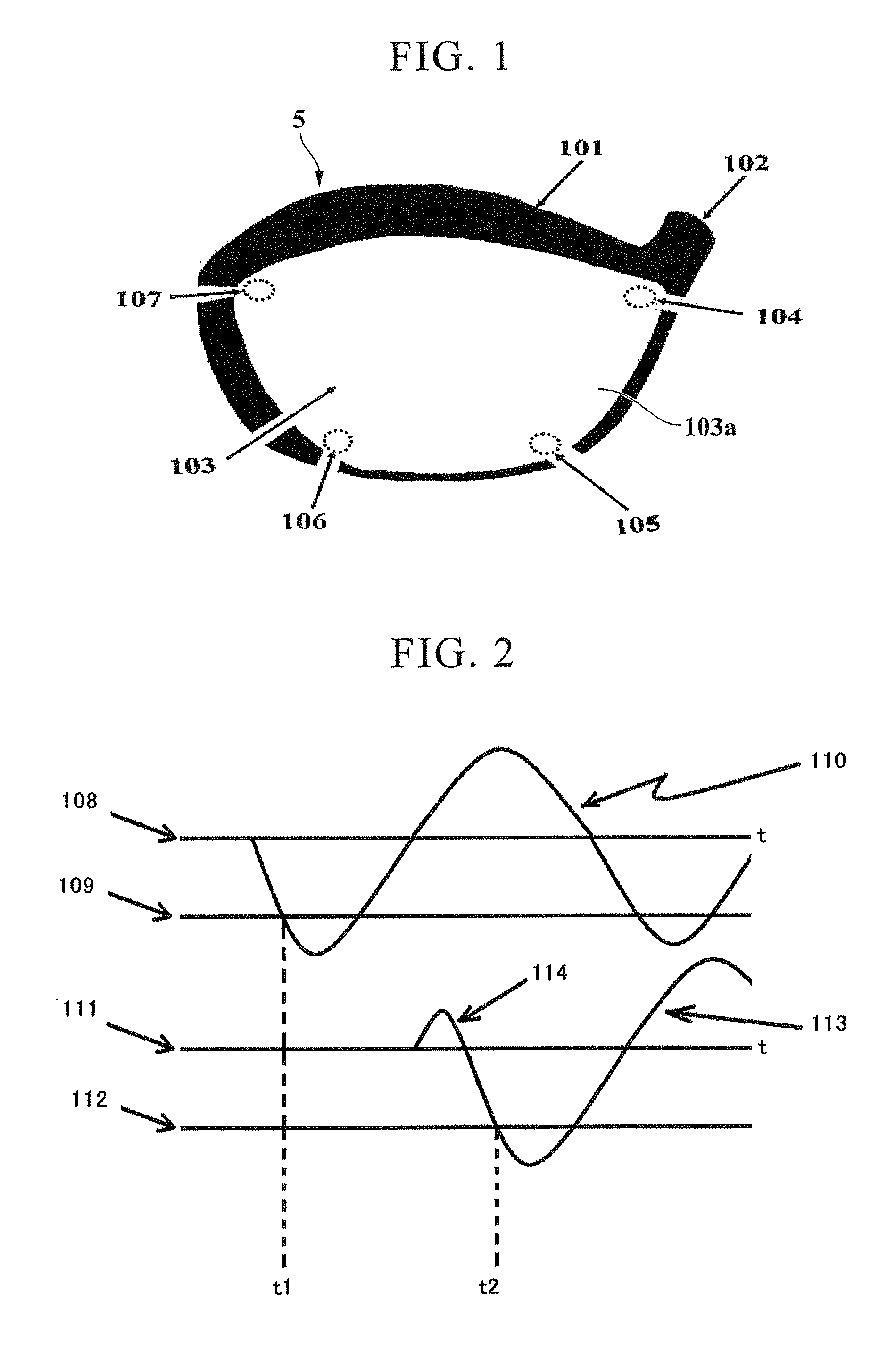
[0290]The inventors first thought that the propagation of the sound wave could be used as a clue in the study of the detection of the hitting position of the face portion by using the sensors attached to the golf club. First, a method of detecting the position of the ball upon hitting of the ball on the basis of the reflection of an ultrasonic wave was considered, but it was difficult to detect the reflection of the sound wave colliding with the ball which is round in shape and collides with the face portion at a high speed.

[0291]Next, instead of the reflection of the sound wave, a method of searching for a sound source generated upon hitting of the ball was considered. However, an expert in searching for sound sources gave the advice that it is not possible to detect the propagation in the horizontal direction (excluding the vertical direction of the surface) of the surface on the grounds that a sound on a rigid metal plate such as titanium is instantly changed to a planar wave as ...

second embodiment

[0317]In addition, as a result of observing an actual golf learner, it was found that the learner performed various actions other than the ball hitting action, such as swinging and missing (an action of just swinging the golf club without hitting the ball) or clipping the ball with the club, as well as an action of just swinging the golf club to hit the ball. Therefore, it was considered that the hitting time point needed to be detected only when the swing action was performed to hit the ball.

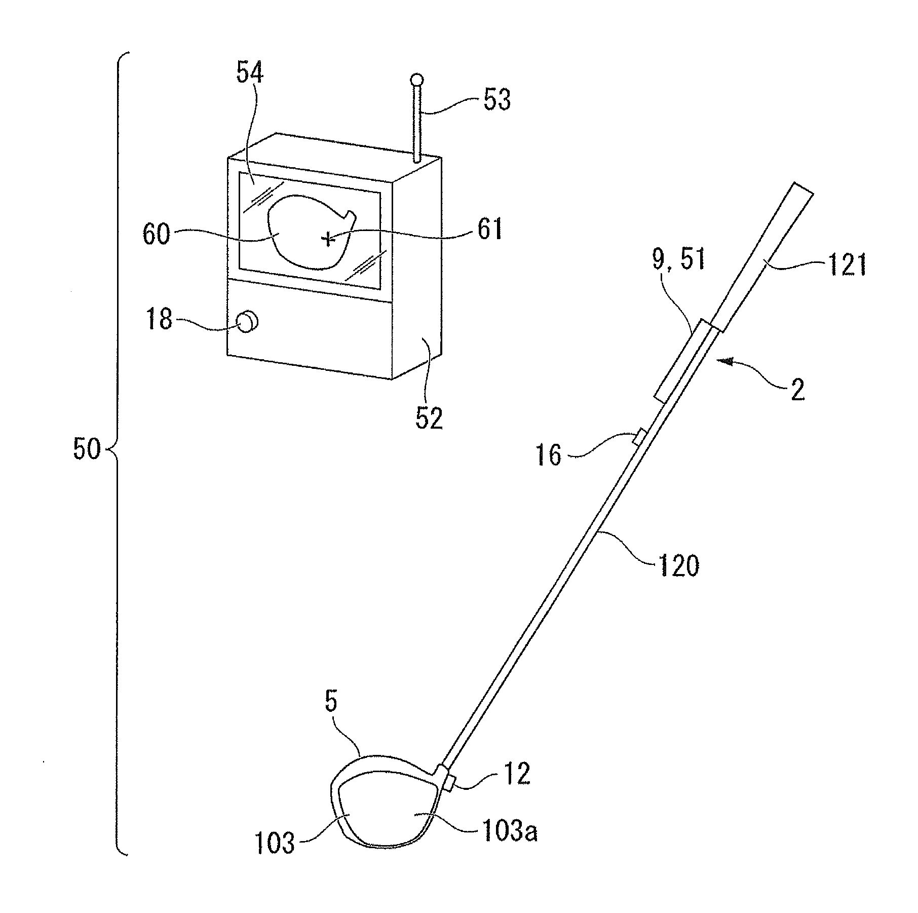
[0318]The inventors attached a three-axis acceleration sensor to the golf club to detect the head speed by using the acceleration sensor, and created a computer program for determining the earnest hitting swing when the head speed exceeded 10 m / s. By using the computer program, the propagation wave arrival detecting circuit and the microcomputer were automatically set to the hitting position detection mode, and only the hitting position detection result was displayed after the hitting action.

[0...


PUM

PropertyMeasurementUnit
Timeaaaaaaaaaa
Poweraaaaaaaaaa
Speedaaaaaaaaaa

Abstract

A hitting position detecting device includes: a golf club which includes a shaft having a grip portion and a head portion having a face portion with a hitting surface and a rear surface and attached to the front end of the shaft; vibration wave sensors which is arranged on the side of the rear surface of the face portion and is fixed to the head portion so as to output electrical signals in accordance with a vibration wave generated upon hitting of the face portion; a calculation unit which detects arrival times in the vibration wave sensors of the vibration wave generated in the face portion upon hitting of a ball on the basis of the electrical signals, calculates a hitting position of the ball in the face portion on the basis of a difference in the plurality of arrival times, and then outputs the result as a hitting position signal; a display unit which displays the hitting position in the face portion on the basis of the hitting position signal output from the calculation unit; and a power source which supplies power to the vibration wave sensors, the calculation unit, and the display unit.

Description

TECHNICAL FIELD[0001]The present invention relates to a hitting position detecting device, and particularly to, a hitting position detecting device capable of simply obtaining a hitting position of a face portion of a golf club head with a high accuracy, a hitting position detecting method, and a method of manufacturing the hitting position detecting device.[0002]Priority is claimed on Japanese Patent Application No. 2007-333133, filed on Nov. 27, 2007, the content of which is incorporated herein by reference.BACKGROUND ART[0003]For a long time, it has been a matter of great interest for learners and beginners to know a hitting stress, a hitting angle, or a ball hitting position (where a ball is hit by a face portion of a club head) regarding a practice golf club.[0004]For this reason, without the need for reference documents, there has been a desire among golf players to know a measurement value of a certain type of a sensor or a transducer (an element for converting a physical cha...

Claims


Application Information

Patent Timeline
IPC IPC(8): A63B69/36H05K13/04A63B53/00A63B53/04A63B102/32
CPCA63B69/3632A63B2024/0043A63B2220/40A63B2220/805A63B2220/808A63B60/42A63B2225/50Y10T29/49826A63B2102/32A63B60/54A63B2220/89A63B53/04
Inventor IWAHASHI, MASAYOSHIIKKA, AKINARIIZUMIKAWA, PETE
Owner MUGEN
Why Eureka
Try Eureka