
Vehicle travel control apparatus

a control apparatus and vehicle technology, applied in the field of vehicle travel control apparatus, can solve the problems of inter-vehicle distance maintenance apparatus and inability to escape an undesirable state of the host vehicle, and achieve the effect of lessening the burden on the driver of the vehicle and improving the safety of travel

Active Publication Date: 2010-12-02
TOYOTA JIDOSHA KK
View PDF10 Cites 35 Cited by
  • Summary
  • Abstract
  • Description
  • Claims
  • Application Information

AI Technical Summary

Benefits of technology

[0007]The invention provides a vehicle travel control apparatus that lessens the burden on the driver of a vehicle by performing a proper travel assist, and improves travel safety by evading an undesirable state of travel of the vehicle.
[0009]According to the foregoing aspect of the invention, the vehicle travel control apparatus includes the output adjustment portion which, when the amount of operation of the operation member increases, adjusts the degree of increase in the output of the vehicle to a degree that is greater the smaller the amount of increase in the amount of operation, on the basis of the state of travel of the vehicle, and which, when the amount of operation of the operation member decreases, adjusts the degree of decrease in the output of the vehicle to a degree that is greater the smaller the amount of decrease in the amount of operation, on the basis of the state of travel of the vehicle. Hence, the vehicle travel control apparatus is able to lessen the burden on the driver of the vehicle by performing a proper travel assist, and is able to improve travel safety by evading an undesirable state of travel of the vehicle.

Problems solved by technology

On the other hand, when the host vehicle is in an undesirable state, it is necessary to evade the undesirable state of the host vehicle.
However, the inter-vehicle distance maintenance apparatus of JP-A-2007-296915 is not able to evade an undesirable state of the host vehicle.

Method used


Image

  • Vehicle travel control apparatus
  • Vehicle travel control apparatus
  • Vehicle travel control apparatus

Examples


first embodiment

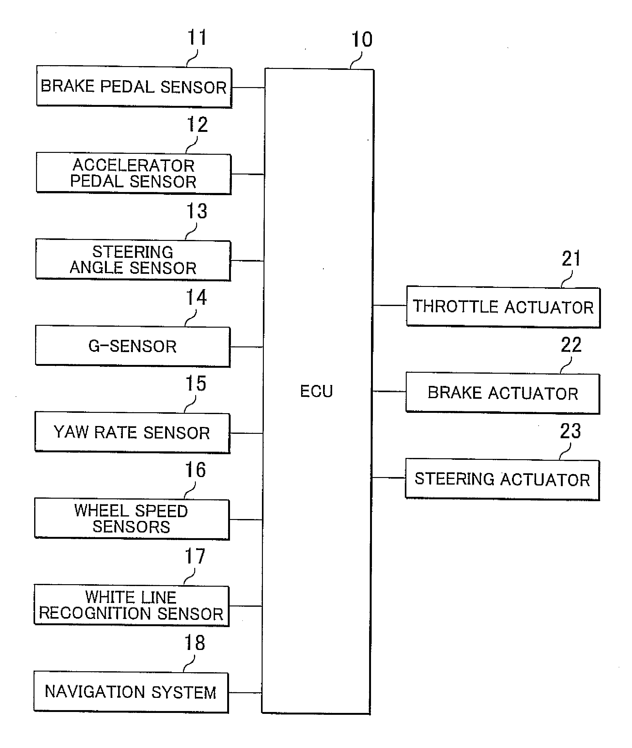
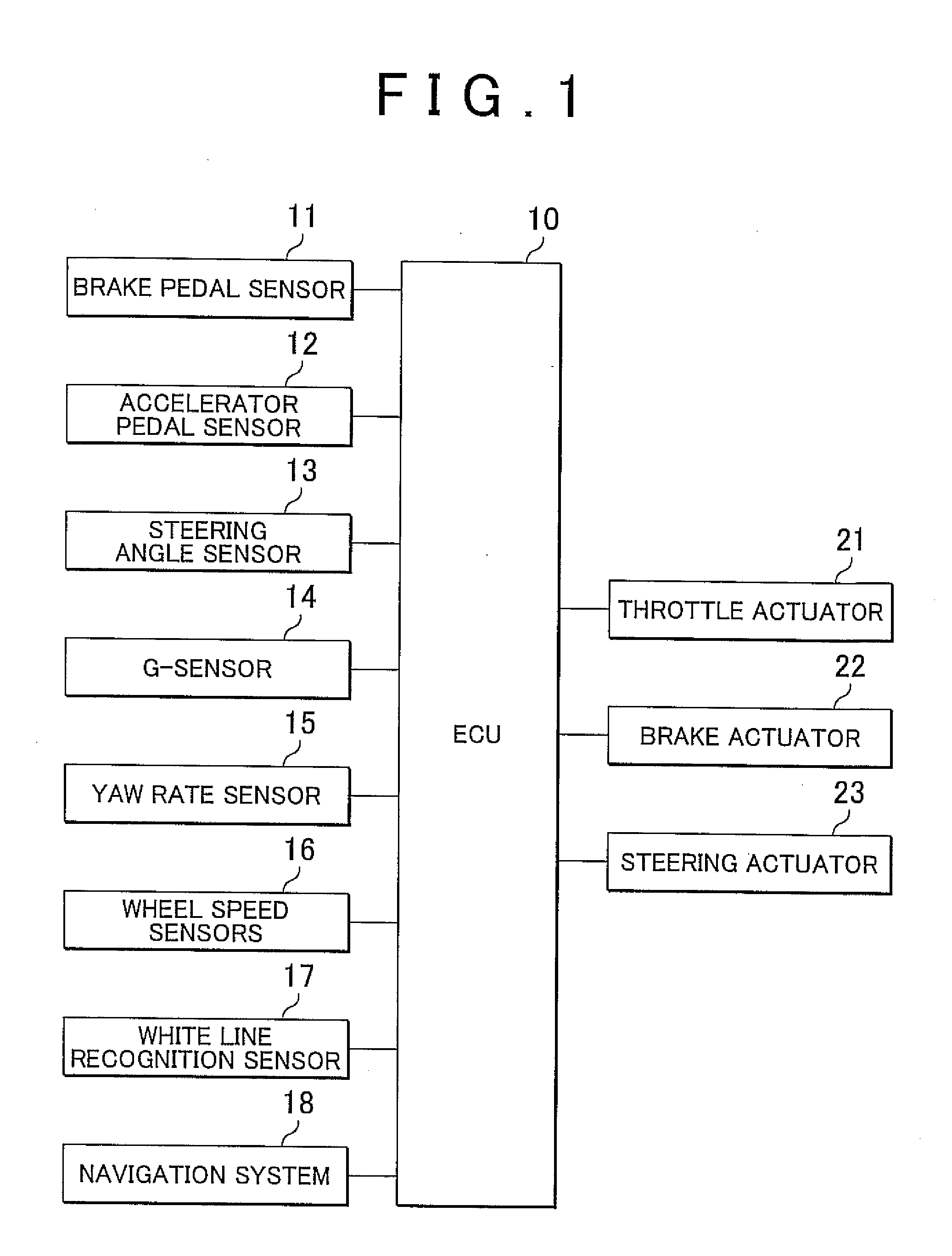
[0027]In the vehicle travel control apparatus of the first embodiment, as shown in FIG. 1, an electronic control unit (ECU) 10 is connected to a brake pedal sensor 11, an accelerator pedal sensor 12, a steering angle sensor 13, a G (acceleration)-sensor 14, a yaw rate sensor 15, wheel speed sensors 16, a white line recognition sensor 17, and a navigation system 18.

[0028]The brake pedal sensor 11 detects the amount of depression of a brake pedal that is depressed by a driver of a vehicle (i.e., the brake pedal stroke or depression force), and outputs the detected amount of depression of the brake pedal to the ECU 10. The accelerator pedal sensor 12 detects the amount of depression of an accelerator pedal that is depressed by the driver (i.e., the accelerator operation amount), and outputs the detected amount of depression of the accelerator pedal to the ECU 10. The steering angle sensor 13 detects the steering angle of the steering handle (wheel) that is operated by the driver, and o...

second embodiment

[0072]The vehicle travel control apparatus of the second embodiment, when there is a preceding vehicle, reduces the degree of increase in the output of the host vehicle relative to the amount of operation of the accelerator pedal, or increases the degree of decrease in the output of the vehicle relative to the amount of operation of the accelerator pedal.

[0073]The vehicle travel control apparatus of the second embodiment will be concretely described. As described above, the vehicle travel control apparatus of the first embodiment controls the traveling of the vehicle by driving the throttle actuator 21, the brake actuator 22 and the steering actuator 23 so that the present acceleration / deceleration of the vehicle becomes equal to the target acceleration / deceleration on the basis of the velocity pattern and the acceleration / deceleration-correspondent map. That is, the control apparatus of the first embodiment controls the traveling of the vehicle by adjusting the output of the host v...

third embodiment

[0084]The vehicle travel control apparatus of the third embodiment alters the degree of increase or the degree of decrease in the output of the host vehicle relative to the amount of operation of the accelerator pedal on the basis of the positional relationship of a preceding vehicle to the dilemma zone.

[0085]The vehicle travel control apparatus of the third embodiment will be concretely described. For comparison, the vehicle travel control apparatus of the second embodiment adjusts the acceleration / deceleration of the host vehicle according to the distance between the host vehicle and a preceding vehicle that travels in front of the host vehicle. In this case, the induction of the host vehicle is adjusted on the basis of the inter-vehicle distance (inter-vehicle time) between the host vehicle and the preceding vehicle. This induction is proper when the host vehicle is traveling following the preceding vehicle. However, in the case where after the host vehicle catches up with the pr...


PUM


Abstract

A vehicle travel control apparatus that controls state of travel of a vehicle by adjusting output of the vehicle relative to amount of operation of an operation member includes: a vehicle travel state detection portion that detects the state of travel of the vehicle; and an output adjustment portion that, when the amount of operation of the operation member increases, adjusts degree of increase in the output of the vehicle to a degree that is greater if amount of increase in the amount of operation of the operating member is smaller, based on the state of travel of the vehicle, and that, when the amount of operation of the operation member decreases, adjusts degree of decrease in the output of the vehicle to a degree that is greater if the amount of decrease in the amount of operation is smaller, based on the state of travel of the vehicle.

Description

INCORPORATION BY REFERENCE[0001]The disclosure of Japanese Patent Application No. 2009-132238 filed on Jun. 1, 2009 including the specification, drawings and abstract is incorporated herein by reference in its entirety.BACKGROUND OF THE INVENTION[0002]1. Field of the Invention[0003]The invention relates to a vehicle travel control apparatus which generate a travel route that a vehicle is to take and generate a velocity pattern according to the travel route, and which control the traveling of the vehicle on the basis of the travel route and the velocity pattern.[0004]2. Description of the Related Art[0005]A vehicle travel control apparatus that generates a target velocity pattern for a travel route of a vehicle, and controls the traveling of the vehicle on the basis of the velocity pattern is described in, for example, Japanese Patent Application Publication No. 2007-296915 (JP-A-2007-296915). In the case of alerting a driver by giving a reaction force to the accelerator pedal under ...

Claims


Application Information

Patent Timeline
Patent Type & Authority Applications(United States)
IPC IPC(8): G06F7/00G08G1/16B60T7/12B60W10/04B60W10/06B60W10/18B60W10/184B60W10/20B60W30/00B60W30/18F02D29/02G08G1/09
CPCG06F7/00G08G1/166G08G1/167
Inventor TAGUCHI, KOJI
Owner TOYOTA JIDOSHA KK
Learn More