
Pool cleaning robot

Active Publication Date: 2010-12-09
MAYTRONICS
View PDF15 Cites 60 Cited by
  • Summary
  • Abstract
  • Description
  • Claims
  • Application Information

AI Technical Summary

Benefits of technology

[0012]The robot may be designed such that motion thereof is independent of the rotation of the auxiliary brushwheel, i.e., the rotation of the auxiliary brushwheel at an elevated speed does not impact the movement of the robot. For example, the auxiliary brushwheel may be disposed at a position sufficiently raised from a planar surface disposed below the robot such that motion of the robot on the planar surface is independent of the rotation of the auxiliary brushwheel. This arrangement ensures that the pressure between the auxiliary brushwheel and the planar surface is sufficiently low that it does not influence the motion of the robot.

Problems solved by technology

In addition, the motion of the track imparts a rotation to the brushwheels, which scrubs the surface of the pool.

Method used


Image

  • Pool cleaning robot
  • Pool cleaning robot
  • Pool cleaning robot

Examples


Embodiment Construction

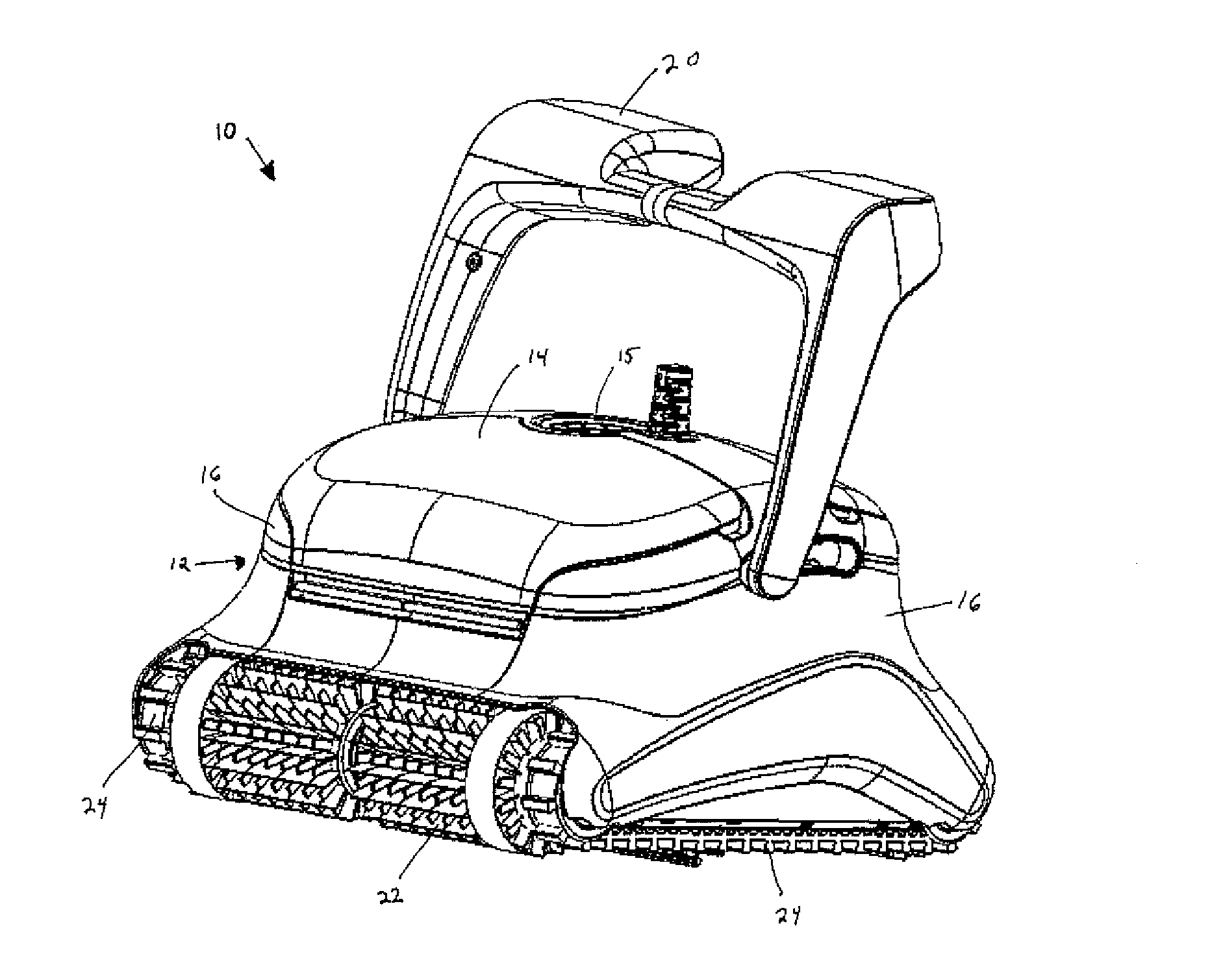
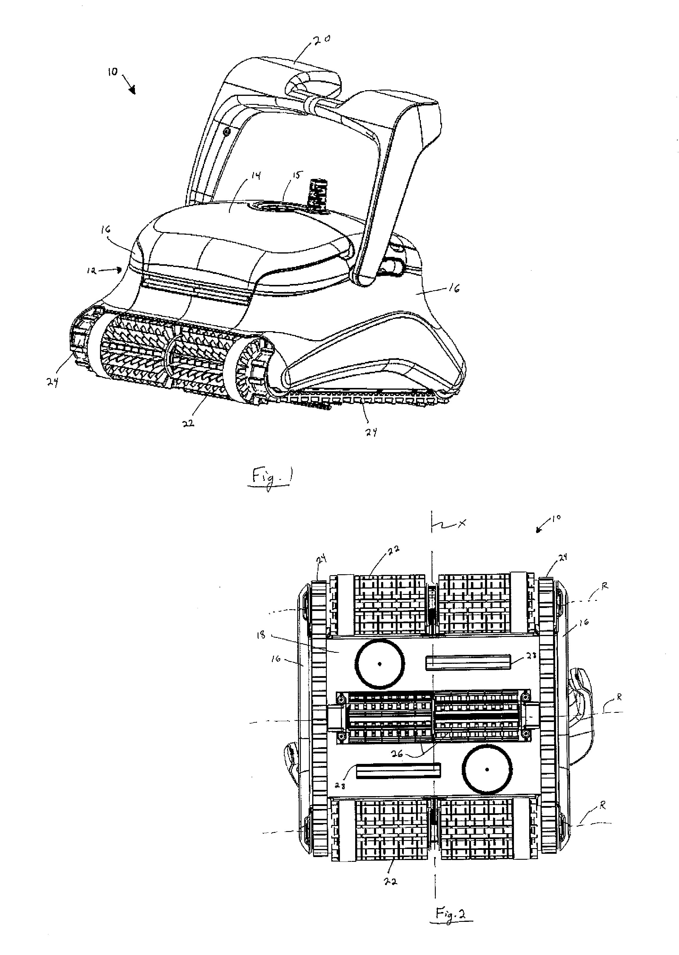
[0050]As illustrated in FIGS. 1 and 2, there is provided a pool cleaning robot, which is generally indicated at 10. The exterior of the robot 10 comprises a housing 12 (which comprises a removable cover 14 with an outlet 15 formed is therein, side panels 16 and a bottom panel 18) and a handle 20 attached thereto. The robot further comprises two main brushwheels 22, with a pair of continuous tracks 24 spanning therebetween, and one or more auxiliary brushwheels 26 attached adjacent the bottom panel 18. Each brushwheel is configured to rotate about a longitudinal axis of rotation R. The interior of the robot 10 comprises one or more motor units for propelling the robot, a filter unit for trapping debris entering the robot, an impeller for generating a suction for drawing water and debris through the robot and which may be driven by one of the motor units (all not shown in FIGS. 1 and 2), and other elements necessary for operation thereof. In the event that the robot 10 comprises two m...


PUM

PropertyMeasurementUnit
Angular velocityaaaaaaaaaa

Abstract

A pool cleaning robot is provided for cleaning a surface of a swimming pool. The robot comprises a main housing, a pair of main wheels disposed at opposite ends of a bottom panel of the housing spanning along a majority of its width and carrying a pair of continuous tracks spanning between edges thereof, the main wheels being configured for rotating at a first angular velocity, at least one inlet being formed in the bottom panel between the main wheels and being configured for intake of water and debris, and at least one auxiliary brushwheel disposed between the main wheels. The robot is configured for rotating the auxiliary brushwheel about an axis of rotation at a second angular velocity which is substantially greater than the first angular velocity.

Description

FIELD OF THE INVENTION[0001]This invention relates to pool cleaning robots, and to filter units for use therewith.BACKGROUND OF THE INVENTION[0002]Pool cleaning robots which automatically scan the floor and / or sidewalls of a swimming pool are well known in the art. These units are powered internally, by one or more battery packs, or externally, by way of a power cable. A robot of this type typically comprises a drive motor, a pump motor with an impeller, a filter, brushwheels, and a track. All of these components are contained within a housing. The housing comprises inlets at the bottom, and an outlet at the top. The robot comprises several sections, which permits at least partial disassembly of the robot.[0003]The drive motor drives the track, which propels the robot. In addition, the motion of the track imparts a rotation to the brushwheels, which scrubs the surface of the pool.[0004]The pump motor drives the impeller to create an upwardly directed suction. This suction draws wate...

Claims


Application Information

Patent Timeline
IPC IPC(8): E04H4/16B01D35/28B01D39/14
CPCE04H4/1654Y10S901/01
Inventor GARTI, EFRAIM
Owner MAYTRONICS
Features
  • Generate Ideas
  • Intellectual Property
  • Life Sciences
  • Materials
  • Tech Scout
  • Unparalleled Data Quality
  • Higher Quality Content
  • 60% Fewer Hallucinations
Learn More